 |
|||
|
Page Title:
Table 3. Group A inspection for device type 01-cont. |
|
||
| ||||||||||
|
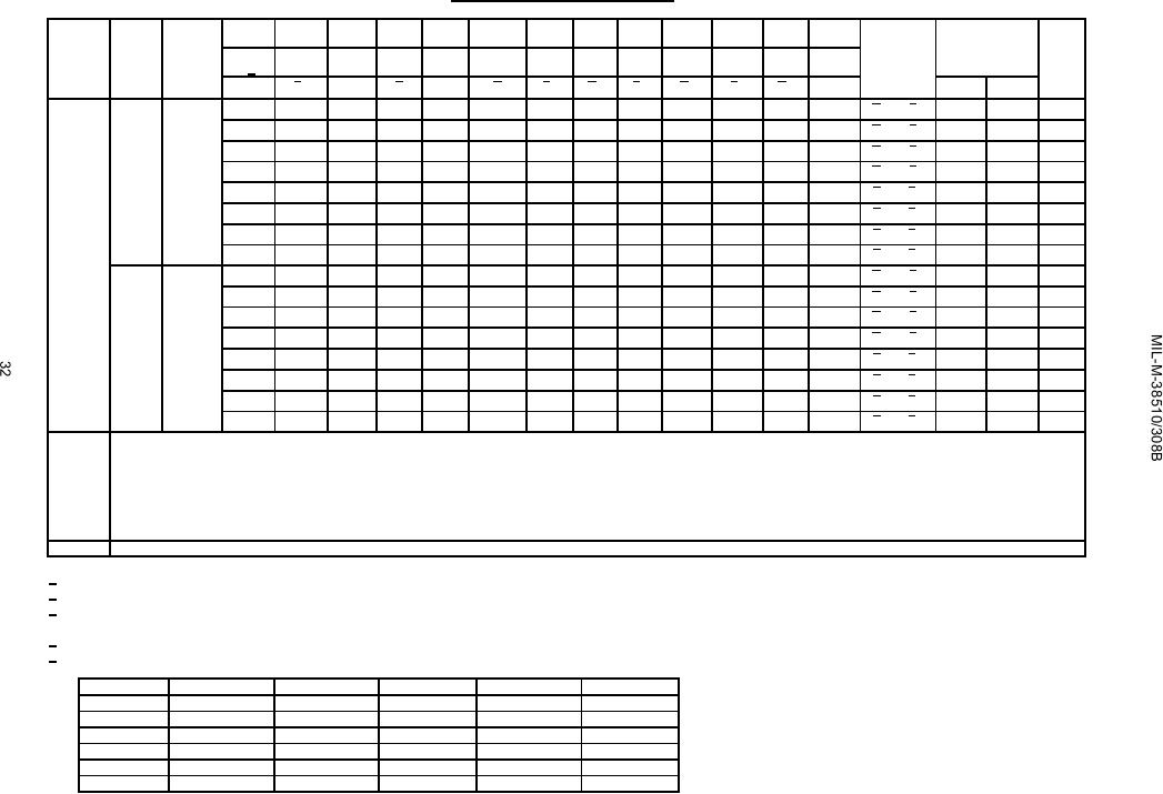
|  TABLE III. Group A inspection for device type 01 - Continued.
Terminal conditions (pins not designated may be high ≥ 2.0 V; low ≤ 0.7 V; or open).
Cases
13
14
15
16
17
18
19
20
21
22
23
24
J, K, Z
MIL-STD-
Subgroup
Symbol
883
Case
16
17
18
19
20
21
23
24
25
26
27
28
Measured
Limits
Unit
3 1/
method
terminal
A=B
Cn+4
VCC
Test no.
Min
Max
F3
P
G
B3
A3
B2
A2
B1
A1
2
38
ns
9
tPHL13
3003
271
GND
GND
GND
GND
GND
GND
5.0 V
A 0 to F 0
Tc = 25C
Fig 4
272
"
GND
"
GND
"
IN
"
"
"
"
A 1 to F 1
"
"
"
"
273
"
GND
"
IN
"
GND
"
A 2 to F 2
"
"
"
"
274
OUT
"
IN
"
GND
"
"
"
A 3 to F 3
"
"
"
"
275
"
GND
"
"
"
"
"
B 0 to F 0
"
"
"
"
276
"
"
"
"
IN
"
"
B 1 to F 1
"
"
"
"
277
"
"
IN
"
GND
"
"
B 2 to F 2
"
"
"
"
278
OUT
IN
"
GND
"
"
"
"
B 3 to F 3
tPLH13
"
279
GND
"
"
"
"
"
"
"
33
"
A 0 to F 0
"
"
"
"
280
"
"
"
"
"
IN
"
A 1 to F 1
"
"
"
"
281
"
"
"
IN
"
GND
"
A 2 to F 2
"
"
"
"
282
OUT
"
IN
"
GND
"
"
"
A 3 to F 3
"
"
"
"
283
"
GND
"
"
"
"
"
B 0 to F 0
"
"
"
"
284
"
"
"
"
IN
"
"
B 1 to F 1
"
"
"
"
285
"
"
IN
"
GND
"
"
B 2 to F 2
"
"
"
"
286
OUT
IN
"
GND
"
GND
"
"
B 3 to F 3
Same tests and terminal conditions as subgroup 9, except Tc = 125C and limits as follows:
10
tPHL1 = 2 to 37 ns; tPLH1 = 2 to 55 ns;
tPHL8 = 2 to 96 ns; tPLH8 = 2 to 100 ns;
tPHL2 and tPLH2 = 2 to 55 ns;
tPHL9 = 2 to 37 ns; tPLH9 = 2 to 48 ns;
tPHL3 and tPLH3 = 2 to 52 ns;
tPHL10 = 2 to 37 ns; tPLH10 = 2 to 48 ns;
tPHL4 = 2 to 57 ns; tPLH4 = 2 to 52 ns;
tPHL11 and tPLH11 = 2 to 64 ns;
tPHL5 = 2 to 42 ns; tPLH5 = 2 to 51 ns;
tPHL12 = 2 to 60 ns; tPLH12 = 2 to 69 ns;
tPHL6 and tPLH6 = 2 to 55 ns;
tPHL13 = 2 to 48 ns; tPLH13 = 2 to 57 ns;
tPHL7 = 2 to 37 ns; tPLH7 = 2 to 46 ns;
Same tests, terminal conditions and limits as subgroup 10, except Tc = -55C
11
1/ Tests shall be performed in sequence.
2/ Input voltages shown are: A = 2.0 volts minimum and B = 0.7 volts maximum.
3/ Output voltages shall be either: (a) H = 2.5 V, minimum and L = 0.4 V, maximum when using a high speed checker double comparator; or
(b) H > 1.5 V and L < 1.5 V when using a high speed checker single comparator.
4/ All functional tests (82 thru 120) require a 1 kΩ pull up resistor between pin 14 and VCC.
5/ IIL limits (mA) min/max values for circuits shown:
Parameter
Test no.
A
B
C
D
IIL1
16
-0.16/-0.40
-0.03/-0.30
-0.16/-0.40
-0.15/-0.38
IIL2
17, 18, 19, 29
-0.48/-1.20
-0.09/-0.90
-0.48/-1.20
-0.45/-1.14
IIL3
21, 22, 23, 24
-0.64/-1.60
-0.72/-1.44
-0.64/-1.60
-0.60/-1.52
IIL4
21, 22, 23, 24
-0.64/-1.60
-0.72/-1.44
-0.64/-1.60
-0.60/-1.52
IIL5
25
-0.80/-2.0
-1.0/-2.0
-0.80/-2.0
-0.75/-1.90
IIL6
26, 27, 28, 29
-0.32/-0.80
-0.09/-0.09
0.32/-0.82
-0.30/-0.76
|
|
Privacy Statement - Press Release - Copyright Information. - Contact Us |