 |
|||
|
Page Title:
Table 1. Electrical performance characteristics-cont. |
|
||
| ||||||||||
|
|  MIL-M-38510/314C
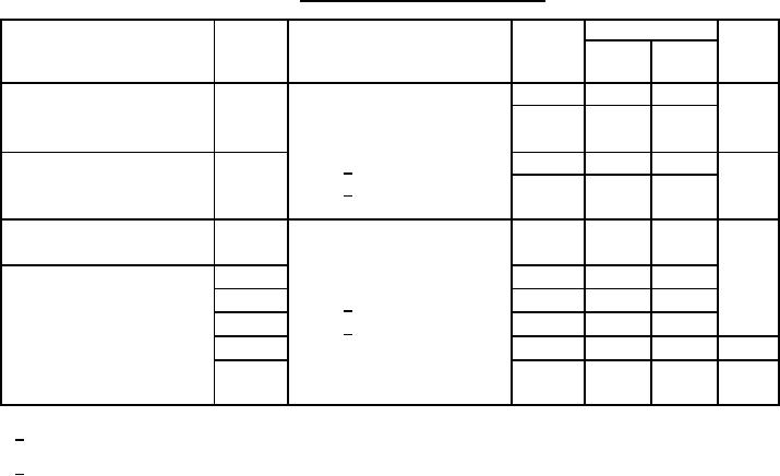
TABLE I. Electrical performance characteristics - Continued.
Test
Symbol
Conditions
Device
Limits
Unit
-55C ≤ TC ≤ +125C
types
Min
Max
unless otherwise specified
Propagation delay time
tPHL2
VCC = 5.0 V
01, 03
5
92
ns
CL = 50 pF 10%
02
5
105
high to low level from input B
RL = 2kΩ 5%
Propagation delay time
tPHL3
Cext = 1/
01, 03
5
48
ns
high to low level from clear
Rext = 1/
02
5
90
Minimum pulse width
tP(MIN)
VCC = 5.0 V
01, 03
308
ns
CL = 50 pF 10%
of Q output
RL = 2kΩ 5%
02
20
91
Width of Q output pulse
tP1
Cext = 2/ 10%
02
70
195
tP2
Rext = 2/ 10%
02
600
850
tP3
s
tP4
01, 03
3.0
6.25
tP5
02
5.5
8.5
ms
1/ For propagation delay tests, see table III for Cext and Rext values.
2/ tP(MIN) test, Cext = open and Rext = 5 kΩ.
tP1 test, Cext = open and Rext = 2 kΩ.
tP2 test, Cext = 80 pF and Rext = 2 kΩ.
tP3 test, Cext = 100 pF and Rext = 10 kΩ.
tP4 test, Cext = 1,000 pF and Rext = 10 kΩ.
tP5 test, Cext = 1F and Rext = 10 kΩ.
6
|
|
Privacy Statement - Press Release - Copyright Information. - Contact Us |
