 |
|||
|
Page Title:
Table 3. Group A inspection for device type 02-cont. |
|
||
| ||||||||||
|
| 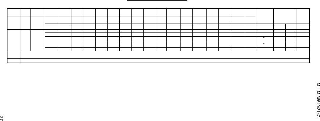 TABLE III. Group A inspection for device type 02 - Continued.
Terminal conditions (pins not designated may be high ≥ 2.0 V, low ≤ 0.7 V, or open).
Cases
1
2
3
4
5
6
7
8
9
10
11
12
13
14
15
16
MIL-
E, F
Subgroup Symbol STD-883
Case
2
3
4
5
7
8
9
10
12
13
14
15
17
18
19
20
Measured
Limits
Unit
method -
2
terminal
Q2
Cext2
Rext2
GND
A2
B2
CLR2
Q1
Cext1
Rext1
Test no.
A1
B1
CLR1
VCC
Min
Max
Q1
Q2
9
tP5
3003
98
OUT
J
J
GND
IN
5.0 V
5.0 V
5.0 V
Q2
5.7
8.0
ms
Tc = 25C
Fig. 4
99
IN
5.0 V
5.0 V
"
OUT
J
J
"
Q1
"
"
"
"
"
"
"
100
IN
5.0 V
"
OUT
"
"
"
"
Q1
"
"
101
GND
IN
"
OUT
"
"
"
"
Q1
"
102
GND
IN
"
"
OUT
"
"
"
Q1
"
"
"
Same tests and terminal conditions as subgroup 9, except TC = +125C and limits are as follows: tPLH1 is 5 to 113 ns; tPLH2 is 5 to 90 ns; tPLH3 is 5 to 105 ns;
10
tPHL1 is 5 to 128 ns; tPHL2 is 5 to 105 ns; tPHL3 is 5 to 90 ns; tP1 is 20 to 91 ns; tP2 is 70 to 195 ns; tP3 is 600 to 850 ns; and tP5 is 5.5 to 8.5 ms.
Same tests and terminal conditions as for subgroup 10, except TC = -55C
11
NOTES:
A. VIN = 3.0 V minimum.
B. VIN = 0.0 V or GND.
C.
Apply input pulse
┌────┐ - - - 2.5 V min/5.5 V max.
──┘
└── 0 V
D. Test numbers 39 through 58 shall be run in sequence.
E. Output voltages shall be either:
H > 1.5 V; L < 1.5 V
F. Rext = 1.4 kΩ minimum to 70 kΩ maximum, connected to VCC; Cext ≤ 1,000 F, connected to Rext terminal.
G. Rext = 2 kΩ 10%, connected to VCC; Cext = 80 pF 10%, connected to Rext terminal.
Rext = 10 kΩ 10%, connect to VCC; Cext = 100 pF 10%, connected to Rext terminal.
I.
J. Rext = 10 kΩ 10%, connect to VCC; Cext = 1.0 F 10%, connected to Rext terminal.
K. Rext = 2 kΩ 10%, connect to VCC.
L. Note F may apply during subgroups 1, 2, and 3 testing if desired.
M. During subgroups 9, 10, 11 testing, Rext and Cext may remain applied on the side of the device not under test if desired.
N. Rext = 10 kΩ 10%, connect to VCC; Cext ≥ 45 pF connected to Rext terminal.
|
|
Privacy Statement - Press Release - Copyright Information. - Contact Us |
