 |
|||
|
Page Title:
Table 3. Group A inspection for device type 03-cont. |
|
||
| ||||||||||
|
| 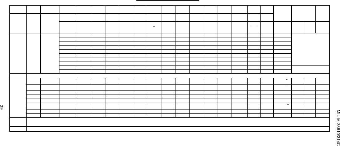 TABLE III. Group A inspection for device type 03 Continued.
Terminal conditions (pins not designated may be high ≥ 2.0 V, low ≤ 0.7 V, or open).
Case
1
2
3
4
5
6
7
8
9
10
11
12
13
14
MIL-STD-
A,B,C,D
Subgroup Symbol
883
Case
2
3
4
6
8
9
10
12
13
14
16
18
19
20
Measured
Limits
Unit
method
2
terminal
Min
Max
Rext
GND
Q
Rint
NC
Cext
Test no.
A1
A2
B1
B2
CLR
Cext
VCC
NC
Q
(see I)
(see I)
7
Truth
3014
36
B
A
A
A
A
L
GND
H
K
K
5.0 V
All
Tc = 25C
table
"
37
"
"
"
B
B
H
"
L
"
"
"
outputs
See notes A, B
test
"
38
"
"
"
B
A
H
"
L
"
"
"
"
"
39
"
"
"
A
A
L
"
H
"
"
"
"
"
40
A
"
"
"
B
H
"
L
"
"
"
"
"
41
A
"
"
"
A
H
"
L
"
"
"
"
"
42
B
"
"
"
A
L
"
H
"
"
"
"
"
43
A
"
"
"
B
H
"
L
"
"
"
"
"
44
"
"
"
"
A
H
"
L
"
"
"
"
"
45
"
B
"
"
A
L
"
H
"
"
"
"
Repeat subgroup 7 at TC = +125 C and TC = -55 C.
8
5
50
ns
1
tPHL1
3003
46
IN
5.0 V
5.0 V
5.0 V
5.0 V
OUT
GND
K
K
5.0 V
A1 to Q
Tc = 25C
61
"
tPHL2
(Fig. 3)
47
GND
GND
IN
5.0 V
5.0 V
OUT
"
K
K
"
B1 to Q
tPHL3
"
48
GND
GND
5.0 V
IN
IN
"
OUT
M
M
"
CLR to Q
32
"
tPLH1
"
49
IN
5.0 V
5.0 V
5.0 V
5.0 V
"
OUT
K
K
"
A1 to Q
38
"
tPLH2
"
50
GND
GND
IN
5.0 V
5.0 V
"
OUT
K
K
"
B1 to Q
49
"
50
"
tPLH3
"
51
GND
GND
5.0 V
IN
IN
OUT
"
M
M
"
CLR to Q
tP(MIN)
"
52
IN
5.0 V
5.0 V
5.0 V
5.0 V
"
OUT
G
"
Q
205
"
s
tP4
"
53
GND
GND
IN
5.0 V
"
OUT
F
N
"
Q
3.5
6.0
Same tests and terminal conditions as subgroup 9 except TC = +125C and limits are as follows: tPHL1 is 50 to 75 ns; tPHL2 is 5 to 92 ns; tPHL3 is 5 to 48 ns; tPLH1 is 5 to 57 ns;
10
tPLH2 is 5 to 74 ns; tPLH3 is 5 to 75 ns; tP(MIN) is 308 ns; and tP4 is 3.0 to 6.25 s.
Same tests and terminal conditions as subgroup 10 except TC = -55C.
11
NOTES:
A. VIN = 3.0 V minimum.
B. VIN = 0.0 V or GND.
C. For circuit D, IIL1 limits are 120 to 360 mA.
D. Test numbers 29 through 45 shall be run in sequence.
E. Output voltages shall be either:
H > 1.5 V; L < 1.5 V
F. Cext connected to Rext/Cext through a 1,000 pF 10% capacitor.
G. Rext/Cext connected to VCC through a 5 kΩ 10% resistor.
I. Note K may apply during subgroups 1, 2, and 3 testing if desired.
J.
Apply input pulse
┌────┐ - - - 2.5 V min/5.5 V max.
──┘
└── 0 V
K. Rext/Cext connected to VCC through a 5 kΩ to 180 kΩ resistor, and Cext connected to Rext/Cext through a ≤ 1,000 F capacitor.
M. Cext connected to Rext/Cext through A ≥ 45 pF capacitor, Rext/Cext connected to VCC through a 10 kΩ 10% resistor.
N. Rext/Cext connected to VCC through a 10 kΩ 10% resistor.
|
|
Privacy Statement - Press Release - Copyright Information. - Contact Us |
