 |
|||
|
Page Title:
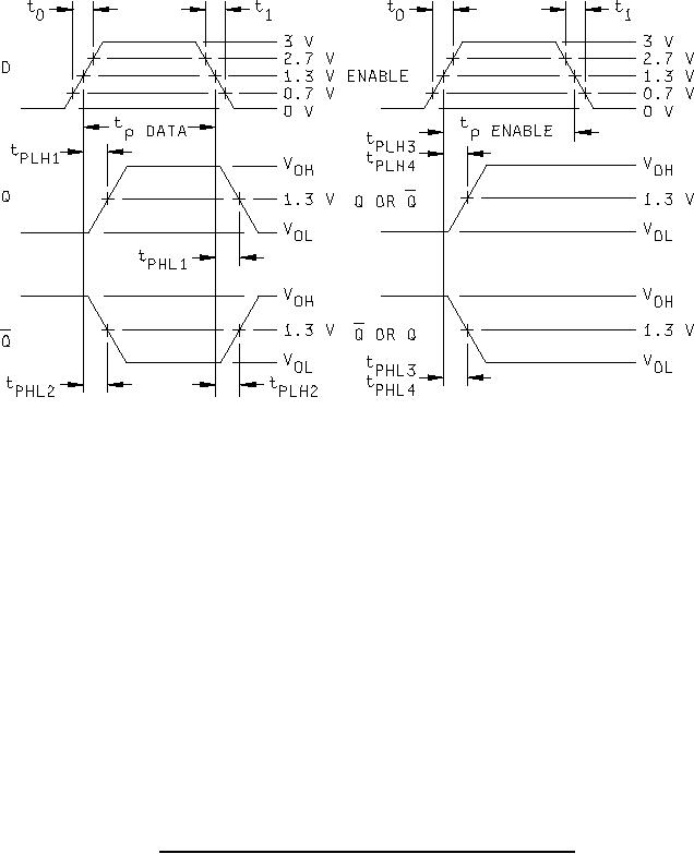
Figure 3. Switching test circuit and waveforms for device types 01 and 04-cont. |
|
||
| ||||||||||
|
|  MIL-M-38510/316E
NOTES:
1. The D input pulse generator has the following characteristics: VGEN = 3 V, t0 ≤ 15 ns, t1 ≤ 6 ns, tP = 30 ns,
and ZOUT = 50Ω except when measuring VSETUP.
2. The enable pulse generator is identical to the D input pulse generator.
3. CL = 50 pF 10% and includes probe and jig capacitance.
4. RL = 2 kΩ 5 percent.
5. All diodes are 1N3064 or equivalent.
6. VSETUP is to be measured 500 ns minimum after input transitions to assure that the device has latched with
minimum setup and maximum hold conditions applied to inputs.
FIGURE 3. Switching test circuit and waveforms for device types 01 and 04 - Continued.
12
|
|
Privacy Statement - Press Release - Copyright Information. - Contact Us |
