 |
|||
|
Page Title:
Table 3. Group A inspection for device type 01 and 04-cont. |
|
||
| ||||||||||
|
| 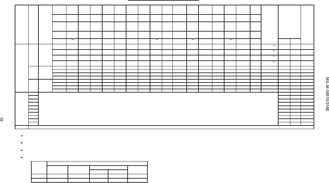 TABLE III. Group A inspection for device type 01 and 04 - Continued.
Terminal conditions (pins not designated may be high ≥ 2.0 V; low ≤ 0.7 V; or open).
Type 01
1
2
3
4
5
6
7
8
9
10
11
12
13
14
15
16
Cases
E, F
Cases
2
3
4
5
7
8
9
10
12
13
14
15
17
18
19
20
2, X
Type 04
2
1
7
12
16
9
15
14
13
11
10
8
4
6
5
3
MIL-STD-
Cases
E, F
Subgroup
Symbol
883
Cases
3
2
9
15
20
12
19
18
17
14
13
10
5
8
7
4
Measured
Limits
Unit
method
2, X
terminal
Test no.
1D
2D
EN 3-4
VCC
3D
4D
4Q
3Q
GND
EN 1-2
2Q
1Q
Min
Max
1Q
4Q
3Q
2Q
9
tPHL4
3003
82
OUT
4.5 V
5.0 V
GND
IN
3
20
ns
EN to 1 Q
Tc = 25C
"
"
"
Fig. 3
83
4.5 V
"
"
IN
OUT
EN to 2 Q
"
84
IN
"
4.5 V
OUT
"
"
"
"
EN to 3 Q
"
85
IN
"
4.5 V
OUT
"
"
"
"
EN to 4 Q
VSUH
"
86
IN
"
"
IN
OUT
1Q
2.5
V
"
87
IN
"
"
IN
OUT
2Q
"
"
"
88
IN
"
IN
OUT
"
3Q
"
"
"
89
IN
"
IN
OUT
"
4Q
"
"
VSUL
"
90
IN
"
"
IN
OUT
1Q
"
0.4
"
"
91
IN
"
"
IN
OUT
2Q
"
"
"
"
92
IN
"
IN
OUT
"
3Q
"
"
"
"
93
IN
"
IN
OUT
"
4Q
"
"
"
10
tPLH1
3
42
ns
TC =125C
tPHL1
"
29
"
tPLH2
"
32
"
Same tests and terminal conditions as for subgroup 9, except TC = +125C and test limits as shown
"
26
"
tPHL2
tPLH3
"
42
"
tPHL3
"
39
"
tPLH4
"
46
"
tPHL4
"
26
"
VSUH
2.5
V
VSUL
0.4
V
Same tests, terminal conditions and limits as for subgroup 10, except TC = -55C.
11
1/ Apply 0V/3V - 5V/0V momentary pulse 500 ns minimum prior to measurement.
2/ A = 2.4 V, B = 0.4 V.
3/ H ≥ 1.5 V, L ≤ 1.5 V.
4/ IIL limits are as follows:
Min/max limits (mA)
Test
Circuit A, B
Circuit C
Circuit D
Circuit E
Device 01
Device 04
IIL1
-.16/-.40
-.0005/-.40
-.03/-.40
-.16/-.40
-.19/-.42
IIL2
-.64/-1.60
0/-1.20
-.12/-1.20
-.64/-1.60
-.75/-1.60
|
|
Privacy Statement - Press Release - Copyright Information. - Contact Us |
