 |
|||
|
Page Title:
Table 3. Group A inspection for device type 01-cont. |
|
||
| ||||||||||
|
| 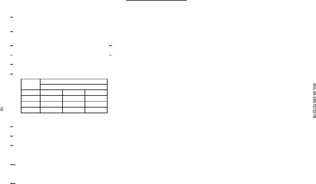 TABLE III. Group A inspection for device type 01 - Continued.
Terminal conditions (pins not designated may be high ≥ 2.0 V; low ≤ 0.7 V; or open).
┌──┐
1/
Apply
- - 2.0 V min./5.5 V max. prior to test after clear pulse.
┘└
0.0 0.2 V
┌──┐
2/
Apply
- - 2.0 V min./5.5 V max. pulse prior to test.
0.0 0.2 V
┘└
3/
Apply 2 pulses prior to test after clear pulse (see 1/).
4/
Apply 4 pulses prior to test after clear pulse (see 1/).
5/
For tests 9 and 13, IIL3 maximum value pulse 4 mA shall be applied to output QA.
6/
IIL limits shall be as follows:
Symbol
Min/Max limits (mA)
Circuit
A
E
B
IIL1
-.15/-.38
-.12/-.36
-.16/-.40
IIL2
-.35/-1.6
-1.0/-2.4
-.35/-1.6
IIL3
-.60/-2.4
-1.3/-3.2
-.60/-2.4
7/
Only a summary of attributes data is required.
8/
A = 2.4 V min. and B = 0.4 V max.
9/
Output voltages shall be either:
a. H ≥ 2.5 V and L ≤ 0.4 V when using a high speed double comparator, or
b. H ≥ 1.5 V and L ≤ 1.5 V when using a high speed single comparator.
10/
FMAX1 and FMAX2 minimum limits specified are the frequency of the input pulse.
The output pulse shall be one half the input frequency when measuring QA.
The output shall be one fifth of the input frequency when measuring QD.
┌──┐
11/
Apply sufficient
- - 2.0 V min./5.5 V max. pulses to set output high prior to test.
┘└
0.0 0.2 V
|
|
Privacy Statement - Press Release - Copyright Information. - Contact Us |
