 |
|||
|
Page Title:
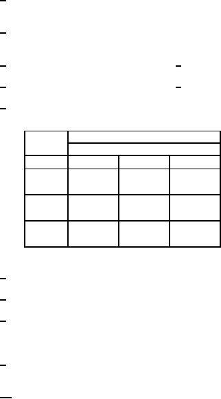
Table 3. Group A inspection for device type 03-cont. |
|
||
| ||||||||||
|
|  MIL-M-38510/327B
┌──┐
1/
Apply
- - 2.0 V min./5.5 V max. prior to test after clear pulse.
┘└
0.0 0.2 V
┌──┐
2/
Apply
- - 2.0 V min./5.5 V max. pulse prior to test.
0.0 0.2 V
┘└
3/
Apply 2 pulses after clear pulse (see 1/).
4/
Apply 4 pulses after clear pulse (see 1/).
5/
IIL limits shall be as follows:
Symbol
Min/Max limits (mA)
Circuit
A
E
B
IIL1
-.15/-.38 -.135/-.37 -.16/-.40
(CLR)
IIL2
-.16/-.40
-.135/-.37
-.16/-.40
(ST9)
IIL3
-.35/-1.6
-1.0/-2.4
-.35/-1.6
6/
Only a summary of attributes data is required.
7/
A = 2.4 V min. and B = 0.4 V max.
8/
Output voltages shall be either:
a. H ≥ 2.5 V and L ≤ 0.4 V when using a high speed double comparator, or
b. H ≥ 1.5 V and L ≤ 1.5 V when using a high speed single comparator.
9/
FMAX1 minimum limits specified is the frequency of the input pulse. The output pulse shall be one half the input
frequency.
┌──┐
10/
Apply sufficient
- - 2.0 V min./5.5 V max. pulses to set output high prior to test.
┘└
0.0 0.2 V
25
|
|
Privacy Statement - Press Release - Copyright Information. - Contact Us |
