 |
|||
|
Page Title:
Table I. Electrical performance characteristics. (Cont) |
|
||
| ||||||||||
|
| 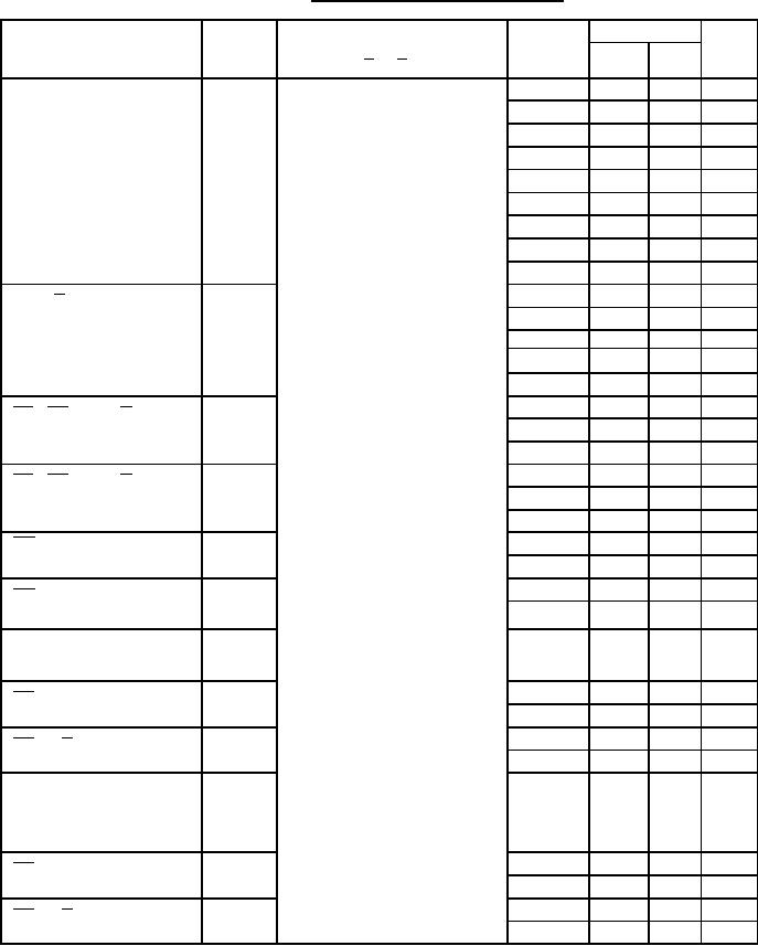 MIL-M-38510/341F
TABLE I. Electrical performance characteristics.
Limits
Test
Symbol
Conditions
Device
Unit
-55C < TC < +125C
types
Min
Max
unless otherwise specified
VCC = 5.0 V, CL = 50 pF 10%
01
ns
3.8
10.5
CP to Q output
tPHL1
02
ns
See figure 4
3.8
10.5
03
ns
2.5
9.5
04
ns
3.5
10.5
05
ns
3.0
11.5
07
ns
1.0
13.0
08
ns
2.5
10.5
09
ns
2.5
10.5
10
ns
2.5
9.5
01
ns
3.8
10.5
tPHL2
CP to Q output
02
ns
3.8
10.5
03, 11
2.5
9.5
ns
04
ns
3.5
10.5
06
ns
4.0
11.0
01
ns
3.2
11.5
tPHL3
SD , CD , to Q, Q
02
ns
3.2
11.5
output (CP high)
03
2.0
9.5
ns
01
ns
3.5
11.5
tPHL4
SD , CD , to Q, Q
02
ns
3.5
11.5
output (CP low)
03
2.5
9.5
ns
tPHL5
04
4.5
15.0
ns
MR Q, output
(CP high)
07
1.0
17.0
ns
04
4.5
15.0
ns
t PHL6
MR to Q output
07
1.0
17.0
ns
(CP low)
Propagation delay
time, low level
to off-state
t PLZ1
05
1.5
7.5
ns
OE to Q output
10
1.0
7.0
ns
06
1.5
7.5
ns
t PLZ2
OE to Q output
11
1.5
7.0
ns
Propagation delay
time high level
to off-state
tPHZ1
05
1.5
8.0
ns
OE to Q output
10
1.0
7.0
ns
tPHZ2
06
1.5
8.0
ns
OE to Q output
11
1.5
7.0
ns
See footnotes at end of table.
8
|
|
Privacy Statement - Press Release - Copyright Information. - Contact Us |
