 |
|||
|
|
|||
| ||||||||||
|
| 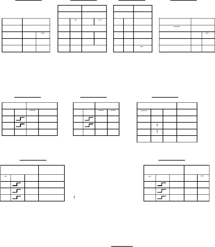 MIL-M-38510/341F
Device type 01
Device type 02
Device type 03
Device type 04
Input
Outputs
Input
Outputs
@ tn
@ tn +1
@ tn
@ tn +1
Q
J
K
Q
Inputs
Outputs
Input
Outputs
J
Q
K
@ tn +1
@ tn
@ tn +1
L
H
No change
L
L
Qn
@ tn1 MR = H
L
L
L
L
H
L
H
Dn
Qn
D
Q
Q
Qn
H
H
L
L
H
H
H
L
H
L
L
L
H
L
H
H
L
H
H
H
L
Toggles
H
H
Qn
tn = Bit time before clock pulse
tn +1 = Bit time after clock pulse
H = High voltage level
L = Low voltage level
Device type 06
Device type 07
Device type 05
Inputs
Outputs
Inputs
Outputs
Inputs
Outputs
CP
D
Q
Qn
Dn
CP
Dn
CP
OE
OE
Qn
MR
H
L
H
H
L
L
L
X
X
L
L
L
L
L
L
H
H
H
H
X
X
H
Z
X
X
H
Z
H
L
L
H
L
X
Q0
Device type 09
Device type 08
Outputs
H = High voltage level
Inputs
Outputs
Inputs
CP
Dn
Qn
L = Low voltage level
CP
Dn
Qn
Qn
E
E
H
X
No change
X = Immaterial
H
X
NC
NC
L
H
H
Z = High impedance
L
H
H
L
= Transition from low to high level
L
L
L
L
L
L
H
Q0 = The level of Q before the indicated
steady-state input conditions were
established
H = High voltage level
H = High voltage level
X = Immaterial
L = Low voltage level
L = Low voltage level
NC = No change
X = Immaterial
FIGURE 3. Truth tables.
19
|
|
Privacy Statement - Press Release - Copyright Information. - Contact Us |
