 |
|||
|
|
|||
| ||||||||||
|
| 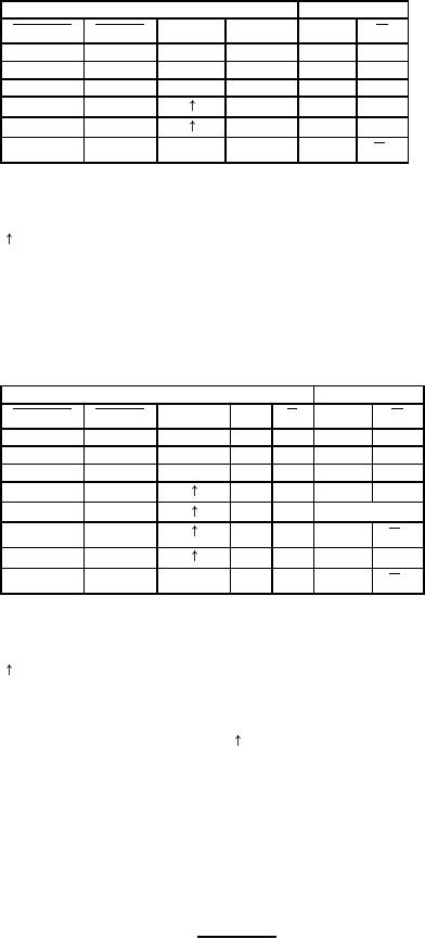 MIL-M-38510/371B
Device type 01
INPUTS
OUTPUTS
CLOCK
D
Q
PRESET
CLEAR
Q
L
H
X
X
H
L
H
L
X
X
L
H
L
L
X
X
H*
H*
H
H
H
H
L
H
H
L
L
H
H
H
L
X
Q0
Q0
H = High level (steady state).
L = Low level (steady state).
X = Irrelevant
= Transition from low to high level
Q0= The level of Q before the incicated steady
state input conditions were established.
*This configuration is nonstable; that is it will not persist
when preset and clear inputs return to their inactive (high) level.
Device type 02
INPUTS
OUTPUTS
CLOCK
J
Q
K
PRESET
CLEAR
Q
L
H
X
X
X
H
L
H
L
X
X
X
L
H
L
L
X
X
X
H*
H*
H
H
L
L
L
H
H
H
H
L
TOGGLE
H
H
L
H
Q0
Q
0
H
H
H
H
H
L
H
H
L
X
X
Q0
Q0
H = High level (steady state)
L = Low level (steady state)
X = Irrelevant
= Transition from low to high level
Q0= The level of Q before the indicated steady
state input conditions were established.
TOGGLE: Each output changes to the complement of its
Previous level on each clock transition.
*This configuration is nonstable; that is, it will not persist when
preset and clear inputs return to their inactive (high) level.
FIGURE 3. Truth tables.
16
|
|
Privacy Statement - Press Release - Copyright Information. - Contact Us |
