 |
|||
|
Page Title:
Table 3. Group A inspection for device type 01-cont. |
|
||
| ||||||||||
|
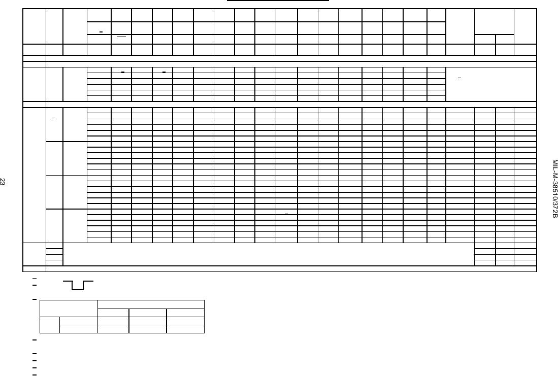
|  TABLE III. Group A inspection for device type 01 - Continued.
Terminal conditions (pins not designated may be high ≥ 2.0 V; low ≤ 0.8 V; or open).
Cases
1
2
3
4
5
6
7
8
9
10
11
12
13
14
15
16
MIL-STD-
E, F
Subgroup Symbol
883
Case
2
3
4
5
7
8
9
10
12
13
14
15
17
18
19
20
Measured
Limits
Unit
method
2 1/
terminal
Test no.
1Q
1D
2D
2Q
3D
3Q
GND
CLK
4Q
4D
5Q
5D
6D
6Q
VCC
Min
Max
CLR
1
ICC
3005
51
GND
GND
GND
GND
GND
GND
GND
GND
5.5 V
VCC
19
mA
Tc = 25C
Same tests, terminal conditions, and limits as subgroup 1, except TC = +125C and VI C tests are omitted.
2
Same tests, terminal conditions, and limits as subgroup 1, except TC = -55C and VI C tests are omitted.
3
7
Truth
3014
52
B 6/
L
A 6/
A
L
A
L
GND
B
L
A
L
A
A
L
4.5 V
TC = 25C table
"
53
A
L
A
A
L
A
L
"
B
L
A
L
A
A
L
"
7/
"
tests
"
54
H
A
A
H
A
H
"
A
H
A
H
A
A
H
"
"
"
55
H
B
B
H
B
H
"
B
H
B
H
B
B
H
"
"
"
56
L
B
B
L
B
L
"
A
L
B
L
B
B
L
"
"
"
57
L
B
B
L
B
L
"
B
L
B
L
B
B
L
"
Same tests and terminal conditions as subgroup 7, except TC = +125C and -55C.
8
9
fMAX
3003
58
3.0 V
OUT
IN
GND
IN
5.0 V
1Q
50
MHz
Tc = 25C
3/
(fig. 4)
59
"
IN
OUT
"
"
"
2Q
"
"
"
60
"
IN
OUT
"
"
"
3Q
"
"
"
61
"
"
"
OUT
IN
"
4Q
"
"
"
62
"
"
"
OUT
IN
"
5Q
"
"
"
63
"
"
"
IN
OUT
"
6Q
"
"
tPLH1
"
64
"
OUT
IN
"
"
"
CLK to 1Q
3
15
ns
"
65
"
IN
OUT
"
"
"
CLK to 2Q
"
"
"
"
66
"
IN
OUT
"
"
"
CLK to 3Q
"
"
"
"
67
"
"
"
OUT
IN
"
CLK to 4Q
"
"
"
"
68
"
"
"
OUT
IN
"
CLK to 5Q
"
"
"
"
69
"
"
"
IN
OUT
"
CLK to 6Q
"
"
"
tPHL1
"
70
"
OUT
IN
"
"
"
CLK to 1Q
5
17
"
"
71
"
IN
OUT
"
"
"
CLK to 2Q
"
"
"
"
72
"
IN
OUT
"
"
"
CLK to 3Q
"
"
"
"
73
"
"
"
OUT
IN
"
CLK to 4Q
"
"
"
"
74
"
"
"
OUT
IN
"
CLK to 5Q
"
"
"
"
75
"
"
"
IN
OUT
"
CLK to 6Q
"
"
"
tPHL4
"
76
IN
OUT
3.0 V
"
2/
"
CLR to 1Q
8
23
"
"
77
3.0 V
OUT
"
"
"
CLR to 2Q
"
"
"
"
78
3.0 V
OUT
"
"
"
CLR to 3Q
"
"
"
"
79
"
"
OUT
3.0 V
"
CLR to 4Q
"
"
"
"
80
"
"
OUT
3.0 V
"
CLR to 5Q
"
"
"
"
81
"
"
3.0 V
OUT
"
CLR to 6Q
"
"
"
10
fMAX
40
MHz
tPLH1 Same tests and terminal conditions as for subgroup 9, except TC = +125C.
3
18
ns
tPHL1
5
20
"
tPHL4
8
26
"
Same tests, terminal conditions and limits as for subgroup 10, except TC = -55C.
11
1/ Terminals not referenced are N/C.
2/ Apply
2.0 V min/4.5 V max
(pulse, prior to test).
-- 0 V
3/ IIL limits shall be as follows:
Min/Max limits in A for circuit
Parameters
A
B
C
IIL
D-inputs
0/-100
CLK/CLR
0/-150
4/ Method 3011 of MIL-STD-883 shall be used, except the output shall be as specified herein, and the output current shall be operating rather than short circuit current.
The output conditions have been chosen to produce a current that closely approximates one half of the true short circuit output current, IOS.
5/ Tests shall be performed in sequence, attributes data only.
6/ A = 2.4 V minimum, B = 0.4 V.
7/ H > 1.5 V, L < 1.5 V.
8/ fMAX minimum limit specified is the frequency of the input pulse. The output frequency shall be one-half of the input frequency.
|
|
Privacy Statement - Press Release - Copyright Information. - Contact Us |