 |
|||
|
Page Title:
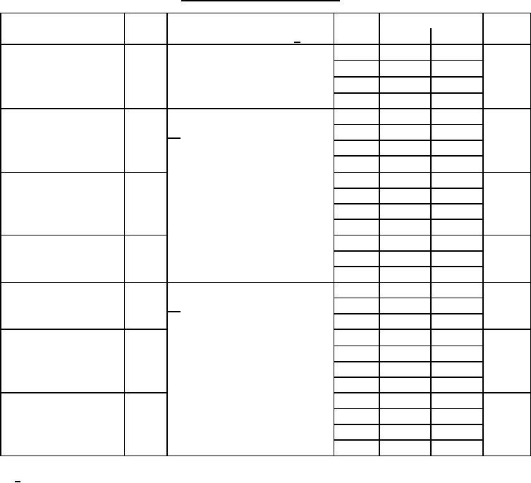
Table 1. Electrical performance characteristics-cont. |
|
||
| ||||||||||
|
|  MIL-M-38510/61C
TABLE I. Electrical performance characteristics Continued.
Test
Symbol
Conditions
Device
Limits
Unit
-55C ≤ TC ≤ +125C 1/
types
Min
Max
VEEL = -3.2 V, VCC = +2.0 V
01
105
CL ≤ 5 pF (output under test)
Maximum clock
FMAX
02
200
MHz
Load = 100Ω to GND
frequency
03
115
04
105
VEEL = -3.2 V, VCC = +2.0 V,
01
1.0
4.9
Transition time,
tTLH
RL
02
1.0
3.6
ns
= 50Ω, CL ≤ 5 pF (output under test)
low to high level
2
03
1.0
4.7
Load = 100Ω to GND (outputs not
04
1.0
5.3
under test)
01
1.0
4.9
Transition time,
tTHL
02
1.0
3.6
ns
high to low level
03
1.0
4.7
04
1.0
5.3
Propagation delay time,
01
1.1
4.9
low to high level (clear or
tPLH1
02
1.0
3.9
ns
preset to output
04
1.0
5.9
Propagation delay time,
VEE = -3.2 V, VCC = +2.0 V,
01
1.1
4.9
high to low level (clear or
tPHL1
RL
02
1.0
3.9
ns
= 50Ω, CL ≤ 5 pF (output under test)
preset to output
2
04
1.0
5.9
Load = 100Ω to GND (outputs not
Propagation delay time,
01
1.4
5.0
low to high level (clock
tPLH2
under test)
02
1.2
3.9
ns
to output
03
1.3
5.3
04
1.0
5.3
Propagation delay time,
01
1.4
5.0
high to low level (clock
tPHL2
02
1.2
3.9
ns
to output
03
1.3
5.3
04
1.0
5.3
1/ Limits are valid provided circuit is in a test socket and transverse air flow of 500 linear ft/min is maintained.
5
|
|
Privacy Statement - Press Release - Copyright Information. - Contact Us |
