 |
|||
|
|
|||
| ||||||||||
|
|  MIL-M-38510/61C
Device types 01 and 02
ASYNCHRONOUS
SYNCHRONOUS
CLR
P/S
Q
C
D
Q
Qn+1
L
X
Qn
L
L
Q
Q
L
H
H
L
H*
L
L
H
L
L
H
H*
H
H
H
H
H*
H*
* This is an unstable condition, when
X = Don't care
C = C E + CC
clear (CLR) and preset (P/S) inputs
return to their low level (inactive state)
*A clock H is a clock transition
these states will not be maintained.
transition from a low to a high state.
Preset (P/S) and clear (CLR) override clock (CC) and clock enable (CE) inputs. Each flip-flop may be clocked
separately by holding the common clock in the low state and using the enable inputs for the clocking function. If the
common clock is to be used to clock the flip-flop, the clock enable inputs must be in the low state. In this case, the
enable inputs perform the function of controlling the common clock. The outputs states of the flip-flop change on the
positive transition of the clock.
Device type 03
SYNCHRONOUS
C
D
Qn+1
L
X
Qn
H*
L
L
H*
H
H
X = Don't care
*A clock H is a clock transition
transition from a low to a high state.
Clocking is common to all six flip-flops. Data transfer is accomplished on positive going transition of the clock.
Device type 04
ASYNCHRONOUS
SYNCHRONOUS
CLR
P/S
Q
Q
J
K
Qn+1
L
L
L
L
Q
Q
Qn
L
H
H
L
H
L
L
H
L
L
H
L
H
H
H
H
H*
H*
H
H
Qn
* This is an unstable condition, when
Output states change on positive
transition of clock for J - K input
clear (CLR) and preset (P/S) inputs
return to their low level (inactive state)
conditions present.
these states will not be maintained.
Preset (P/S) and clear (CLR) override the clock. The output states of the flip-flop change on the positive transition of
the clock.
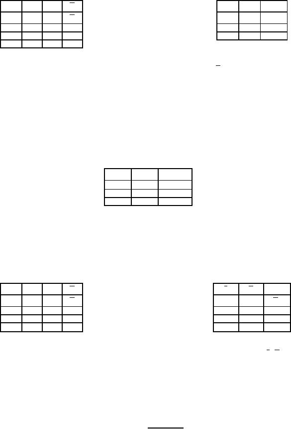
FIGURE 2. Truth tables.
12
|
|
Privacy Statement - Press Release - Copyright Information. - Contact Us |