 |
|||
|
Page Title:
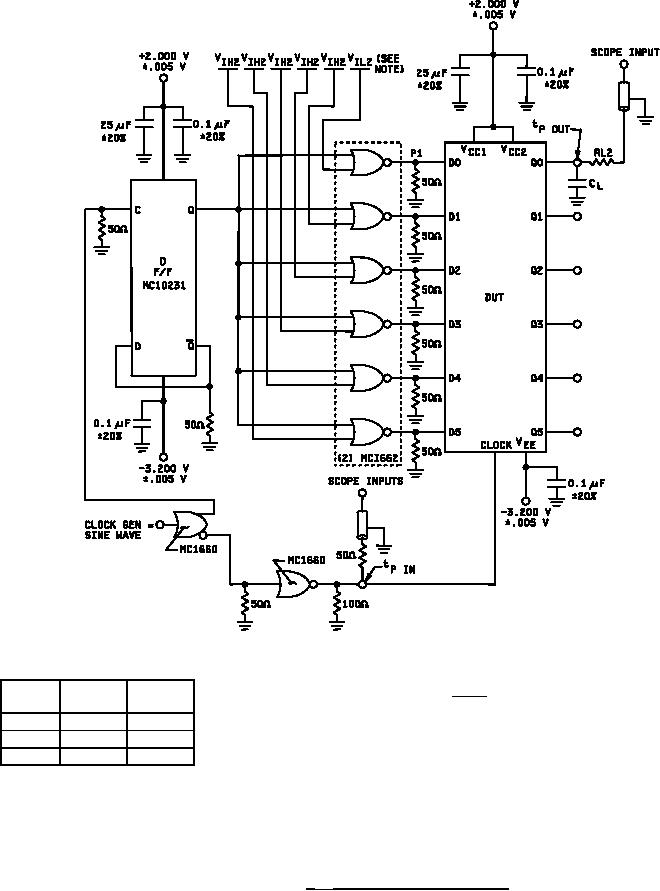
Figure 9. FMAX test circuit for device type 03. |
|
||
| ||||||||||
|
|  MIL-M-38510/61C
All resistors 5%
GENERATOR CHARACTERISTICS
VIL2
TC
VIH2
RL
= 50Ω 5%
10 mV
10 mV
2
25C
SCOPE INPUT = 50Ω to GND
+1.11 V +0.31 V
125C
CL (test jig) ≤ 5 pF
+1.24 V +0.36 V
-55C
+1.01 V +0.28 V
NOTE:
The flip-flop under test will have a "VIL2" applied to the NOR gate and the remaining Nor gates
will have a "VIH2" applied.
FIGURE 9. FMAX test circuit for device type 03.
19
|
|
Privacy Statement - Press Release - Copyright Information. - Contact Us |
