 |
|||
|
Page Title:
Table 1. Electrical performance characteristics-cont. |
|
||
| ||||||||||
|
|  MIL-M-38510/62B
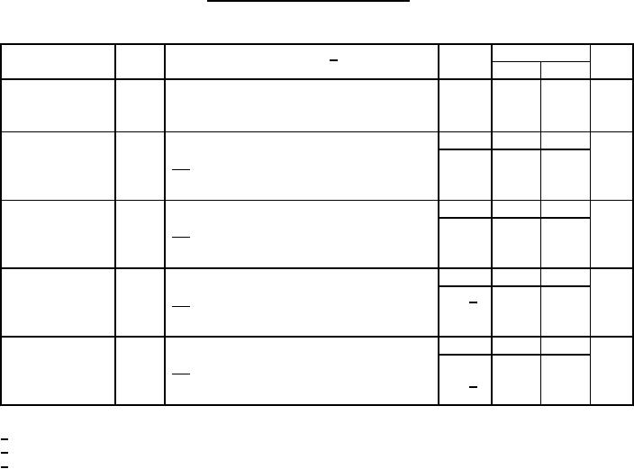
TABLE I. Electrical performance characteristics Continued.
(Limits are valid provided circuit is in a test socket and transverse
air flow of 500 linear ft/min is maintained.)
Units
Limits
Device
Test
Symbol
Conditions 1/
type
-55C ≤ TC ≤ 125C
Min
Max
A
Low-level input
All
0.3
---
VEE = -5.2 V, VCC = 0 V
IIL
current
VIL1 = -1.850 V at +25C, -1.820 V at +125C,
-1.920 V at -55C.
ns
Transition time,
01
1.0
4.1
tTLH
VEEL = -3.2 V, VCC = +2.0 V
low-to-high level
02
1.0
5.3
RL
= 50 Ω, CL ≤ 5 pF (output under test)
2
Load = 100 Ω to GND (outputs not under test)
Transition time,
01
1.0
4.1
ns
VEEL = -3.2 V, VCC = +2.0 V
tTHL
high-to-low level
02
1.0
5.3
RL
= 50 Ω, CL ≤ 5 pF (output under test)
2
Load = 100 Ω to GND (outputs not under test)
ns
Propagation delay
All
1.0
4.7
VEEL = -3.2 V, VCC = +2.0 V
tPLH
time, low-to-high
02 3/
1.0
5.9
RL
= 50 Ω, CL ≤ 5 pF (output under test)
level
2
Load = 100 Ω to GND (outputs not under test)
Propagation delay
All
1.0
4.7
tPHL
VEEL = -3.2 V, VCC = +2.0 V
ns
time, high-to-low
RL
= 50 Ω, CL ≤ 5 pF (output under test)
level
02 3/
1.0
5.9
2
Load = 100 Ω to GND (outputs not under test)
1/
Complete terminal conditions shall be as specified in table III.
2/
Applicable to "B" inputs only.
3/
Applicable to "Common" input only.
5
|
|
Privacy Statement - Press Release - Copyright Information. - Contact Us |