 |
|||
|
Page Title:
Table 1. Electrical performance characteristics-cont. |
|
||
| ||||||||||
|
|  MIL-M-38510/650B
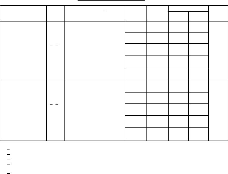
TABLE I. Electrical performance characteristics Continued.
Test
Symbol
Conditions 1/
Device
Limits
Unit
VCC
-55C ≤ TC ≤ +125C
types
Min
Max
unless otherwise specified
Propagation delay
CL = 50 pF +10 percent
tPHL,
01
4.5 V
ns
3
21
times
tPLH
02
4.5 V
3
23
4/ 5/
03
4.5 V
3
26
04
4.5 V
6
41
05
4.5 V
4
29
CL = 50 pF +10 percent
Transition delay
ns
tTHL,
01
4.5 V
3
20
times
tTLH
02
4.5 V
3
20
4/ 5/
03
4.5 V
3
20
04
4.5 V
3
20
05
4.5 V
3
20
1/
Complete terminal conditions shall be as specified in table III.
2/
Guaranteed but not tested.
3/
Power dissipation capacitance (CPD) per gate.
Tested at VCC = 4.5 V at +125C for sample testing and VCC = 4.5 V at +25C for screening. Guaranteed at other VCC
4/
voltages and temperatures, see table IA and exception in 4.4.1d.
5/ For propagation and transition delay times at VCC = 2.0 V, increase limit by a factor of 5.
For propagation and transition delay times at VCC = 6.0 V, decrease limit by a factor of 0.85.
8
|
|
Privacy Statement - Press Release - Copyright Information. - Contact Us |
