 |
|||
|
Page Title:
Figure 3. Switching time test circuit and waveforms. |
|
||
| ||||||||||
|
| 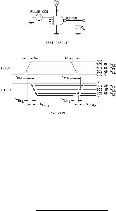 MIL-M-38510/650B
NOTES:
1. CL = 50 pF 10%, includes probe and jig capacitance.
2. Input pulse shall have the following characteristics: tr = tf ≤ 6 ns; PRR ≤ 1MHz; duty cycle = 50%.
3. All unused inputs are tied to VCC.
4. tTHL1 tTHL2 = tTHL; tTLH2 tTLH1 = tTLH
FIGURE 3. Switching time test circuit and waveforms.
16
|
|
Privacy Statement - Press Release - Copyright Information. - Contact Us |
