 |
|||
|
Page Title:
Figure 2. Truth tables (Device type 07) |
|
||
| ||||||||||
|
| 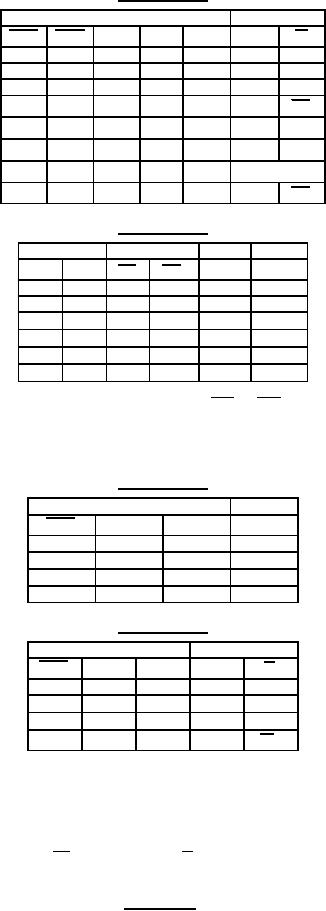 MIL-M-38510/653B
Device type 05
Inputs
Ouputs
PRE
CLR
CLK
J
K
Q
Q
L
H
X
X
X
H
L
H
L
X
X
X
L
H
L
L
X
X
X
H*
H*
↓
H
H
L
L
Q0
Q0
H
H
H
L
H
L
↓
H
H
L
H
L
H
↓
H
H
H
H
Toggle
↓
H
H
H
X
X
Q0
Q0
Device type 06
Inputs
Data enable
Data
Output
CLR
CLK
E1
E2
D
Q
H
X
X
X
X
L
L
L
X
X
X
Q0
↑
L
H
X
X
Q0
↑
L
X
H
X
Q0
↑
L
L
L
L
L
↑
L
L
L
H
H
For device type 06: When either OE1 or OE2
(or both) is (are) high, the output is disabled to the
high-Z state; however, sequential operation of the
flip-flops is not affected.
Device type 07
Inputs
Output
CLR
CLK
D
Q
L
X
X
L
↑
H
H
H
↑
H
L
L
H
L
X
Q0
Device type 08
Inputs
Outputs
CLR
CLK
D
Q
Q
L
X
X
L
H
↑
H
H
H
L
↑
H
L
L
H
H
L
X
Q0
Q0
* = This configuration is nonstable
X = Pins have no effect on output
H = High level voltage
L = Low level voltage
↑ = Low-to-high transition of the clock
↓ = High-to-low transition of the clock
Q0 (Q0) = The level of Q (Q) before the indicated steady-state
input conditions were established
FIGURE 2. Truth tables Continued.
16
|
|
Privacy Statement - Press Release - Copyright Information. - Contact Us |
