 |
|||
|
Page Title:
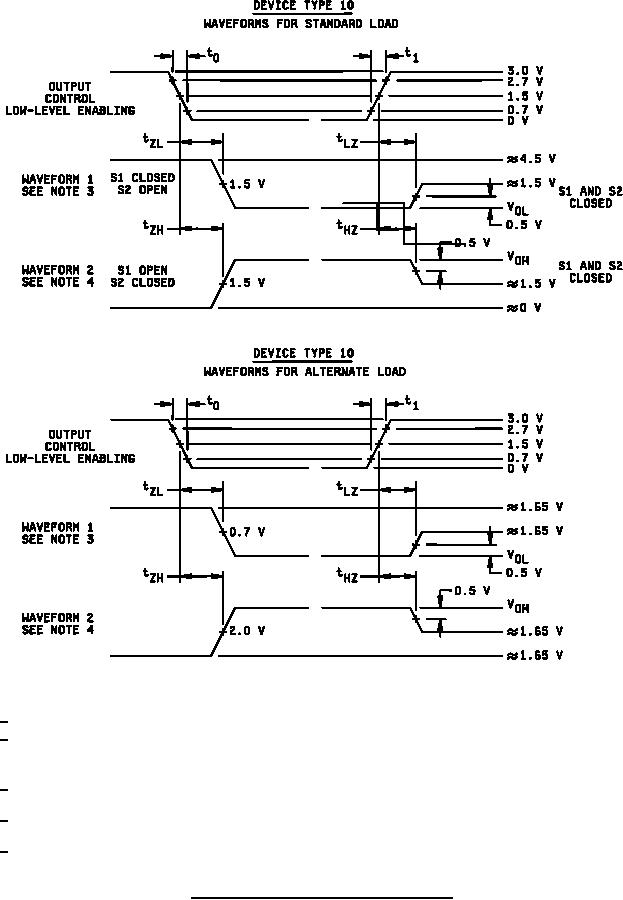
4. Switching time test circuit for device type 10 waveforms for alternate load |
|
||
| ||||||||||
|
|  MIL-M-38510/70C
NOTES:
1/ Pulse generator has the following characteristics: t1 = t0 ≤ 2.5 ns, PRR ≤ 1 MHz, ZOUT ≈ 50 Ω.
2/ Capacitor CL includes probe, jig and wiring capacitance value is 50 pF 10% for all tests when the alternate
load is used. Value is 50 pF 10% for tPHL, tPLH, tZH and tZL tests and 15 pF minimum for tLZ and tHZ tests
when the standard load is used.
3/ Waveform 1 is for an output with internal conditions such that the output is low except when disabled
by the output control.
4/ Waveform 2 is for an output with internal conditions such that the output is high except when disabled
by the output control.
5/ Manufacturer may test with either the standard load circuit or the alternate load circuit at his option.
FIGURE 4. Switching time test circuit for device type 10 - Continued.
15
|
|
Privacy Statement - Press Release - Copyright Information. - Contact Us |
