 |
|||
|
|
|||
| ||||||||||
|
| 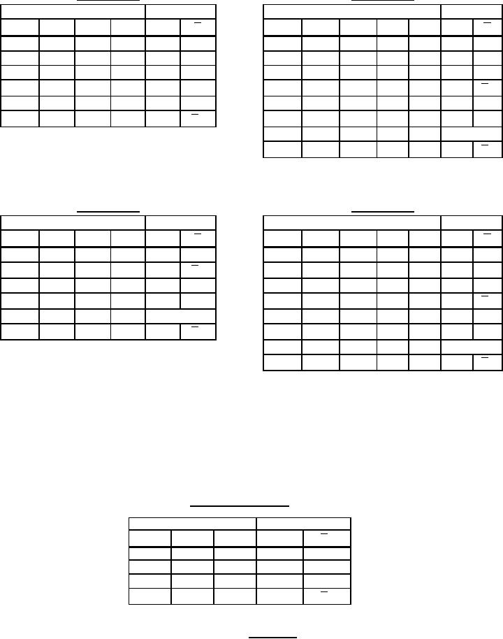 MIL-M-38510/71D
Device type 02
Device type 01
Inputs
Outputs
Inputs
Outputs
Preset
Clear
Clock
J
K
Q
Preset
Clear
Clock
D
Q
Q
Q
L
H
X
X
H
L
L
H
X
X
X
H
L
H
L
X
X
L
H
H
L
X
X
X
L
H
L
L
X
X
H*
H*
L
L
X
X
X
H*
H*
↑
↓
H
H
H
H
L
H
H
L
L
Q0
Q0
↑
↓
L
L
H
H
H
H
L
H
L
H
H
↓
H
H
L
H
L
H
H
H
L
X
Q0
Q0
↓
H
H
Toggle
H
H
H
H
H
X
X
Q0
Q0
Device type 03
Device type 04
Inputs
Outputs
Inputs
Outputs
Preset
Clear
Clock
J
K
Q
Preset
Clock
J
K
Q
Q
Q
L
X
X
X
H
L
L
H
X
X
X
H
L
↓
H
L
X
X
X
L
H
H
L
L
Q0
Q0
↓
H
L
H
L
L
L
X
X
X
H*
H*
H
↓
↓
L
H
L
H
H
H
L
L
Q0
H
Q0
↓
↓
H
H
Toggle
H
H
H
L
H
L
H
↓
H
H
L
H
L
H
H
H
X
X
Q0
Q0
↓
H
H
Toggle
H
H
H
H
H
X
X
Q0
Q0
H = High level (steady state).
L = Low level (steady state).
X = Irrelevant.
↑ = Transition from low to high level.
↓ = Transition from high to low level.
Q0 = The level of Q before the indicated input conditions were established.
Toggle: Each output changes to the complement of its previous level on each active transition (pulse) of the clock.
* This configuration is unstable; that is, it will not persist when preset and clear inputs return to their inactive (high)
level.
Device types 05 and 06
(each flip-flop)
Inputs
Outputs
Clear
Clock
D
Q
Q†
L
X
X
L
H
↑
H
H
L
H
↑
L
L
H
H
H
L
X
Q0
Q0
† = device type 06 only.
Figure 3. Truth table.
15
|
|
Privacy Statement - Press Release - Copyright Information. - Contact Us |
