 |
|||
|
Page Title:
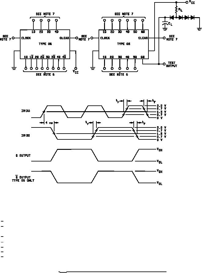
Figure 14. fMAX waveforms and test circuit for device types 05 and 06. |
|
||
| ||||||||||
|
|  MIL-M-38510/71D
NOTES:
1/ tf = tr ≤ 2.5 ns; IN(A) and IN(B)
2/ IN(A) PRR = 75 MHz 50% dc, IN(B) PRR = 37.5 MHz 50% dc, for subgroup 9;
IN(A) PRR = 55 MHz 50% dc, IN(B) PRR = 27.5 MHz 50% dc, for subgroups 10 and 11.
3/ CL = 50 pF 10% including jig and probe capacitance.
4/ RL = 280 Ω 5%.
5/ All diodes are 1N3064 or equivalent.
6/ All load circuits are as shown for 6Q.
7/ See table III for input conditions.
FIGURE 14. fMAX waveforms and test circuit for device types 05 and 06.
27
|
|
Privacy Statement - Press Release - Copyright Information. - Contact Us |
