 |
|||
|
Page Title:
Table 1. Electrical performance characteristics-cont. |
|
||
| ||||||||||
|
|  MIL-M-38510/757C
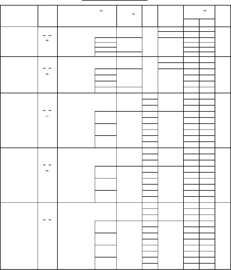
TABLE I. Electrical performance characteristics - Continued.
Test and
Device
VCC
Test Conditions 1/
Group A
Limits 1/
Unit
Symbol
type 2/
MIL-STD-883
-55C ≤ TC ≤ +125C
subgroups
test method
+3.0 V ≤ VCC ≤ +5.5 V
Min
Max
unless otherwise specified
A
5.5 V
Three-state
VOUT = GND
03-05
1, 3
-0.5
IOZL
4/ 5/
output leakage
10, 11
2
-10.0
7/
current low
1
M
-1.0
03-05, 11
3020
D
-3.0
P, L, R
-20.0
F
03, 05
-20.0
A
5.5 V
Three-state
VOUT = VCC
03-05
1, 3
0.5
IOZH
output leakage
4/ 5/
10, 11
2
10.0
current high
7/
1
M
03-05, 11
1.0
3021
D
3.0
P, L, R
20.0
20.0
F
03, 05
Positive-going
V
VT+
For input under test
3.0 V
0.9
2.2
02
1, 2, 3
threshold
VIN = GND
4.5 V
1.35
3.2
voltage
All other inputs
4/ 5/
3006
5.5 V
1.65
3.9
8/
at VCC or GND
M
02
3.0 V
1
0.9
2.2
5.5 V
1.65
3.9
D
3.0 V
0.9
2.2
5.5 V
1.65
3.9
3.0 V
0.9
2.2
P, L, R, F
5.5 V
1.65
3.9
Negative-going
02
1, 2, 3
V
VT-
For input under test
3.0 V
0.5
2.1
threshold
VIN = GND
4.5 V
0.9
3.15
voltage
All other inputs
4/ 5/
5.5 V
1.1
3.85
3006
9/
at VCC or GND
M
02
3.0 V
1
0.5
2.1
5.5 V
1.1
3.85
D
3.0 V
0.5
2.1
5.5 V
1.1
3.85
P, L, R, F
3.0 V
0.5
2.1
5.5 V
1.1
3.85
Hysteresis voltage
Calculated value
VH
3.0 V
0.3
1.2
V
02
1, 2, 3
(VH = VT+ - VT-)
4.5 V
0.4
1.4
4/ 5/
5.5 V
0.5
1.6
M
3.0 V
0.3
1.2
02
1
5.5 V
0.5
1.6
D
3.0 V
0.3
1.2
5.5 V
0.5
1.6
P, L, R
3.0 V
0.3
1.2
5.5 V
0.5
1.6
3.0 V
0.3
1.4
F
5.5 V
0.5
1.9
See footnotes at end of table.
9
|
|
Privacy Statement - Press Release - Copyright Information. - Contact Us |