 |
|||
|
Page Title:
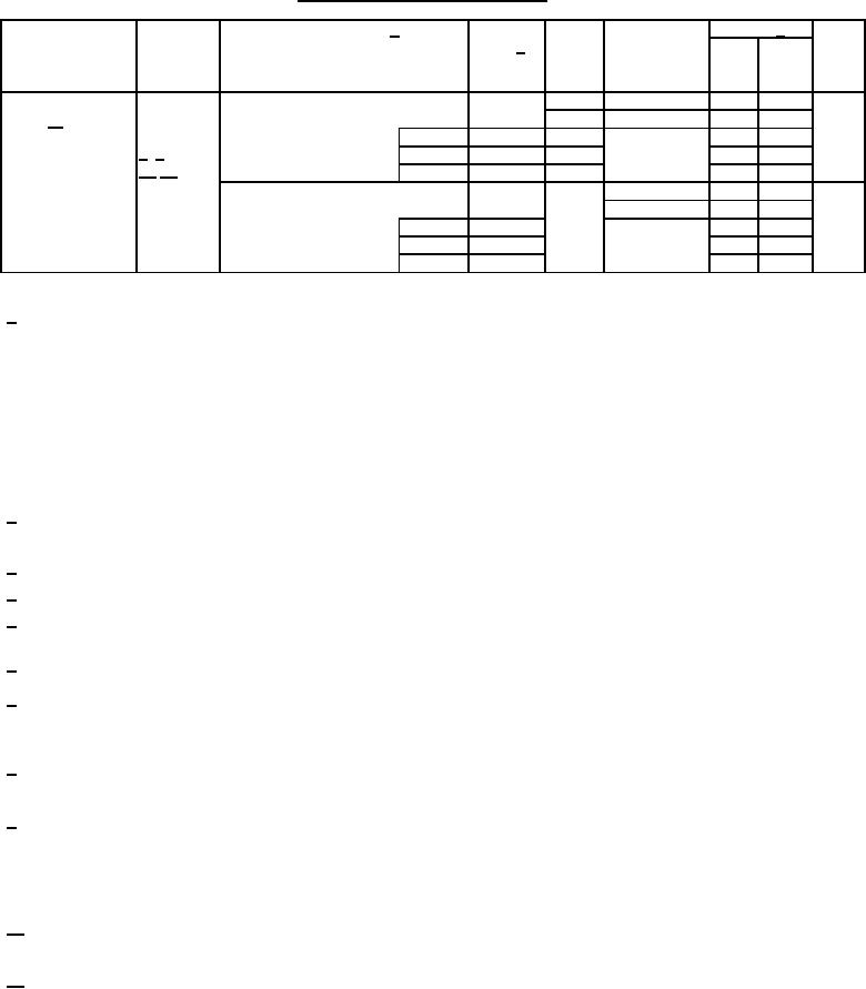
Table 1. Electrical performance characteristics-cont. |
|
||
| ||||||||||
|
|  MIL-M-38510/758B
TABLE I. Electrical performance characteristics Continued.
Unit
Limits 1/
Test and
Symbol
Test conditions 1/
Group A
Device
VCC
-55C ≤ TC ≤ +125C
MIL-STD-883
subgroups
type 2/
Min
Max
test method
3.0 V ≤ VCC ≤ 5.5 V
unless otherwise specified
Propagation
tPHL3,
CL = 50 pF
02
3.0 V
9, 11
1.0
15.5
ns
delay time,
tPLH3
RL = 500Ω
10
1.0
17.0
E3 to On
see figure 3
M
02
1.0
15.5
9
3003
4/ 5/
D
02
1.0
15.5
10/11/
P, L, R
02
1.0
15.5
ns
CL = 50 pF
02
9, 11
1.0
11.5
4.5 V
RL = 500Ω
10
1.0
13.5
see figure 3
9
M
02
1.0
11.5
D
02
1.0
11.5
1.0
11.5
P, L, R
02
1/ Each input/output, as applicable, shall be tested at the specified temperature for the specified limits. Output terminals not
designated shall be high level logic, low level logic, or open, except as follows:
a. VIC (pos) tests, the GND terminal can be open. TC = +25C.
b. VIC (neg) tests, the VCC terminal shall be open. TC = +25C.
c. All ICC tests, the output terminal shall be open. When performing these tests, the current meter shall be
placed in the circuit such that all current flows through the meter.
For negative and positive voltage and current values, the sign designates the potential difference in reference to GND and
the direction of current flow, respectively; and the absolute value of the magnitude, not the sign, is relative to the minimum
and maximum limits, as applicable, listed herein.
2/ The word "All" in the device type column means non-RHA limits for all devices types. M, D, P, L, and R in the conditions
column specify the postirradiation limits for those device types specified in the device type column.
3/ This test is guaranteed, if not tested, to the limits specified in table I.
4/ RHA samples do not have to be tested at -55C and +125C prior to irradiation.
5/ When performing postirradiation electrical measurements for any RHA level, TA = +25C. Limits shown are guaranteed at
TA = +25C 5C.
6/ Transmission driving tests are performed at VCC = 5.5 V dc with a 2 ms duration maximum.
7/ Power dissipation capacitance (CPD) determines the no load dynamic power consumption,
PD = (CPD + CL) (VCC x VCC)f + (ICC x VCC) and the dynamic current consumption, IS = (CPD + CL)VCCf + ICC. For both CPD and
IS, f is the frequency of the input signal.
8/ See EIA/JEDEC STD. No. 78 for electrically induced latch-up test methods and procedures. The values listed for Itrigger and
Vover are to be accurate within 5 percent.
9/ Tests shall be performed in sequence, attributes data only. Functional tests shall include the truth tables and other logic
patterns used for fault detection. Functional tests shall be performed in sequence as approved by the qualifying activity on
qualified devices. H ≥ 2.5 V, L < 2.5 V; high inputs = 3.7 V and low inputs = 0.6 V for VCC = 4.5 V and H ≥ 1.5 V, L < 1.5 V;
high inputs = 2.5 V and low inputs = 0.45 V for VCC = 3.0 V. Tests at VCC = 3.0 V are for RHA specified devices only
(TA = +25C 5C). Functional tests at VCC = 3.0 V are worst case for RHA specified devices.
10/ Devices are tested at VCC = 3.0 V and VCC = 4.5 V at TC = +125C for sample testing and at VCC = 3.0 V and VCC = 4.5 V at
TC = +25C for screening. Other voltages of VCC and temperatures are guaranteed, if not tested. See 4.4.1d.
11/ AC limits at VCC = 5.5 V are equal to the limits at VCC = 4.5 V and guaranteed by testing at VCC = 4.5 V. Minimum ac limits
for VCC = 5.5 V are 1.0 ns and guaranteed by guardbanding the VCC = 4.5 V minimum limits to 1.5 ns. For propagation
delay tests, all paths must be tested.
10
|
|
Privacy Statement - Press Release - Copyright Information. - Contact Us |
