 |
|||
|
Page Title:
Table 1. Electrical performance characteristics and post irradiation end-point electrical parameter limits-cont. |
|
||
| ||||||||||
|
|  MIL-M-38510/762A
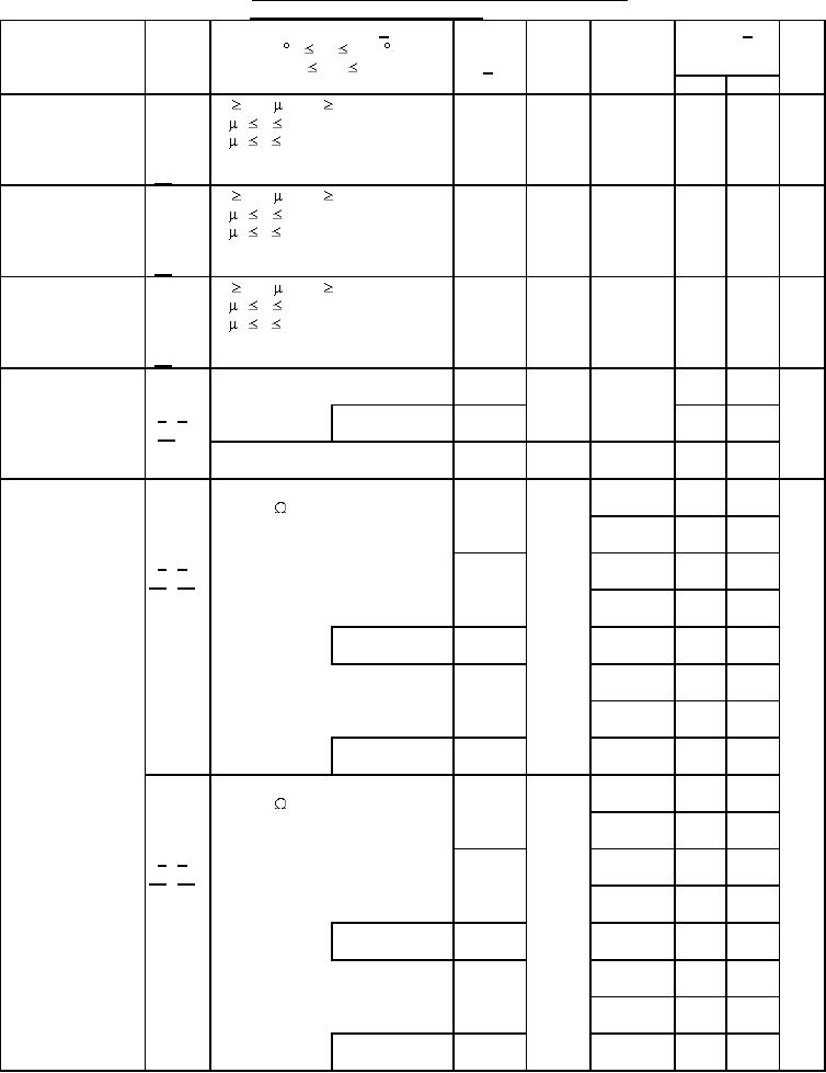
Table I. Electrical performance characteristics and post irradiation
end-point electrical parameter limits. - Continued.
Test and
Symbol
Test conditions 1/
VCC
Group A
Limits 1/
Unit
Device
MIL-STD-883
subgroups
-55 C TC +125 C
type
test method
+4.5 V VCC +5.5 V
2/
unless otherwise specified
Min
Max
ICC
All
5.5 V
2
200
mA
Latch-up
tw 100 s, tcool tw
input/output
5 s tr 5 ms
positive over-
(O/I1+) 5 s tf 5 ms
current
Vtest = 6.0 V, VCCQ = 5.5 V
11/
Itrigger = +120 mA
ICC
All
5.5 V
2
200
mA
Latch-up
tw 100 s, tcool tw
input/output
5 s tr 5 ms
negative over-
5 s tf 5 ms
(O/I1-)
current
Vtest = 6.0 V, VCCQ = 5.5 V
11/
Itrigger = -120 mA
All
5.5 V
2
100
mA
Latch-up supply
ICC
tw 100 s, tcool tw
input/output
5 s tr 5 ms
over-voltage
(O/V2) 5 s tf 5 ms
Vtest = 6.0 V, VCCQ = 5.5 V
11/
Vover = 9.0 V
Truth table test
VIL = 0.45 V
All
3.0 V
7
L
H
3014
VIH = 2.5 V
4/ 5/
Verify output VO
M, D, L, R
02, 03,
L
H
07
12/
VIL = 0.6 V, VIH = 3.7 V
All
4.5 V
7, 8
L
H
Verify output VO
01, 05
3.0 V
9, 11
1.0
18.0
ns
Propagation delay
tPHL1
CL = 50 pF
time,
RL = 500
tPLH1
select to output
See figure 4
10
1.0
22.0
3003
4/ 5/
02, 06
9, 11
1.0
15.0
13/ 14/
10
1.0
19.5
M, D, L, R
02
9
1.0
15.0
03, 04
9, 11
1.0
12.5
07, 08
10
1.0
15.0
M, D, L, R
03, 07
9
1.0
12.5
01, 05
4.5 V
9, 11
1.0
13.0
tPHL1
CL = 50 pF
RL = 500
tPLH1
See figure 4
10
1.0
15.5
4/ 5/
02, 06
9, 11
1.0
11.0
13/ 14/
10
1.0
14.0
M, D, L, R
02
9
1.0
11.0
03, 04
9, 11
1.0
9.5
07, 08
10
1.0
11.5
M, D, L, R
03, 07
9
1.0
9.5
See footnotes at end of table.
8
|
|
Privacy Statement - Press Release - Copyright Information. - Contact Us |