 |
|||
|
Page Title:
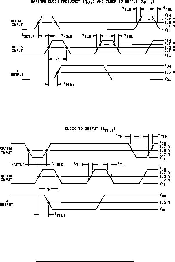
Figure 5. Switching test circuits and waveforms for device type 02. |
|
||
| ||||||||||
|
|  MIL-M-38510/9E
NOTES:
1. Serial input characteristics: For fMAX, PRR = 5 MHz at TC = 25C, PRR = 3.5 MHz at -55C ≤ TC ≤ 125C. For
tPLH1, PRR = 500 kHz, tP = tSETUP + tHOLD, tSETUP = 30 ns, tHOLD = 0 ns, tTHL = tTLH ≤ 10 ns.
2. Clock input characteristics: For fMAX, PRR = 10 MHz at TC = 25C, PRR = 7 MHz at -55C ≤ TC ≤ 125C. For
tPLH1, PRR = 1 MHz, tP = 35 ns, tTHL = tTLH ≤ 10 ns.
3. Clear = 4.5 V, preset enable = GND, preset A thru E = OPEN.
NOTES:
1. Serial input characteristics: PRR = 500 kHz, tTHL = tTLH ≤ 10 ns tP = tSETUP + tHOLD, tSETUP = 30 ns, tHOLD = 0 ns.
2. Clock input characteristics: PRR = 1 MHz, tTHL = tTLH ≤ 10 ns, tP = 35 ns..
3. Clear = 4.5 V, preset enable = GND, preset A thru E = OPEN.
FIGURE 5. Switching test circuits and waveforms for device type 02 - Continued.
31
|
|
Privacy Statement - Press Release - Copyright Information. - Contact Us |
