 |
|||
|
|
|||
| ||||||||||
|
|  MIL-M-46659C(MU)
3.5 Performance.
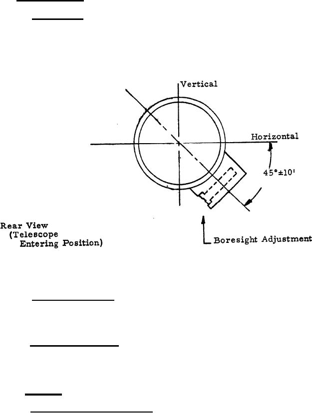
3. 5.1 Orientation. - With the geometric axis of the gimbal tube parallel
to the cylindrical 1936 inch mounting surface, the mount shall be positioned
at an angle of 45 degrees plus or minus 10 minutes from the horizontal as shown
in Figure I. From the above position the leading edge (front) of the lower
locking tooth shall be 20 degrees plus or minus 2 degrees to the right of a
vertical plane pas sing through the geometric axis of the gimbal tube.
Figure I
3.5.2 Azimuth movement. - Rotation of the azimuth adjustment screw (near-
est telescope entering end) shall move the gimbal tube in a horizontal plane through
an excursion of a minimum of 13 mils to the right and mils to the left from
the midpoint position established in accordance with 3.5.1.
3.5.3 Elevation movement. - Rotation of the elevation adjustment screw (farther
from telescope entering end) shall move the gimbal tube in a vertical plane through
a minimum excursion of 13 mils elevation and 13 mils depression from the midpoint
position established in accordance with 3.5.1.
3.6 Torque.
3.6.1 Ring, externally threaded. - The Ring, 7659771, shall be torqued at
final assembly to between 16 and 20 inch pounds with the mount at stadard ambient
temperature (plus 60 degrees to 90 degrees Fahrenheit).
3.
|
|
Privacy Statement - Press Release - Copyright Information. - Contact Us |
