 |
|||
|
|
|||
| ||||||||||
|
|  MIL-M-48557A(AR)
adding the movement of the first reading to the movement of the
second reading. The total movement allowed shall be as
specified in 3.8.8 for elevations of zero 800, 1100 and 1333
mils. The above procedure shall be performed at each of the
elevation settings.
4.8.14 Azimuth correction. Position the mount as specified
in 3.6 and place Sight Device 10549200 on the mounting surface
for the telescope. Affix leveling assembly 11836289 to the
sighting device and adjust level so that the bubble in the
level vial is centered when viewed through the mirror of the
level vial holder. Use this level for a11 leveling throughout
the azimuth correction test where the cant level vial is used.
(After level vial bubble is centered, do not readjust level for
rest of the test.) Set the vertical line of the reticle into
coincidence with the vertical line of the wall target (see
sketch Figure 2). The pitch and cross level vials shall be set
at zero. Energize the fixture to produce cant angle of 88.9
mils (5 degrees) , as indicated on the fixture. Then cant the
mount an equal amount in the opposite direction until the level
vial bubble in the leveling assembly is, centered. Energize the
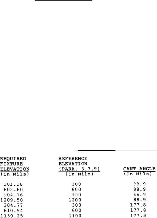
fixture through 301.18 mils of elevation from the canted plane
as indicated on the fixture. Table IV can be used for direct
elevation readings on the fixture. Set the pitch level vial
bubble to the level position. Set the corresponding azimuth
correction into the sight device and insert the pin into place.
Sight through the device and observe where the reticle center
line falls with respect to the tolerance line on the wall
target. Azimuth correction tests shall be performed in the
left and right direction as specified in 3.8.9. The above
procedure shall be performed at each of the elevation settings
in accordance with the applicable cant angles applied to the
fixture and mount. Azimuth corrections and tolerance for same
shall be as specified in 3.8.9.
TABLE IV. Azimuth
correction
tests.
18
|
|
Privacy Statement - Press Release - Copyright Information. - Contact Us |
