 |
|||
|
Page Title:
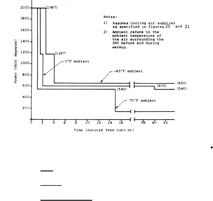
Figure 18. Maximum IMU 115-VAC, 400-Hz 3-Phase Power Requirements |
|
||
| ||||||||||
|
|  MIL-N-81604C(AS)
Figure 18. Maximum IMU 115-VAC, 400-Hz
3-Phase Power Requirements
3.5.1.8.2 Size - The IMU shall conform to the outline and mount-
*
ing drawing in figure 19.
*
3.5.1.8.3 Cooling - Figures 20 thru 22 specify the cooling
requirements and the pressure drop of the IMU.
.
3.5.1.8.4 Cooling Air Valve - An air control valve may be
required in the aircraft to control cooling air to the IMU
whenever the flow rate/temperature operating points would other-
*
wise fall above the maximum flow rate curves in figures 20 and
21. Flow rates above the maximum flow rate curve shall cause no *
damage, but may degrade accuracy and affect system response time.
An electrical control signal for the valve will be provided by the
86
|
|
Privacy Statement - Press Release - Copyright Information. - Contact Us |
