 |
|||
|
|
|||
| ||||||||||
|
|  --
MIL-N-81604C(AS)
3.5.1.9.1 IMU to Test Equipment Signals - The IMU shall provide
the following listed output signals on the test connector.
Mode Indication - The IMU shall provide a four-line *
a.
discrete output code which shall identify the
specific mode in which the IMU is currently operat-
+
ing. This output code shall include internal
submodes in the operation sequence.
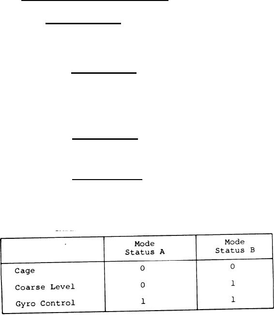
Mode Status A - This signal shall indicate
(1)
the status or mode of operation of the IMU
in conjunction with Mode Status B and
*
table XVIII. This output has a true state
*
of +3.8 1.4 volts d-c and a false state of
*
+0.25 0.25 volts d-c when looking into an
open circuit.
Mode Status B - This signal is identical in
(2)
type and level with that of Mode Status A
and indicates status or mode of the IMU in
conjunction with Mode Status A and table XVIII. *
Mode Status C - This is a spare status line.
(3)
The output characteristics are the same as
Mode Status A and B.
Mode Status D - Same as Mode Status C.
(4)
TABLE XVIII. MODE INDICATION
Malfunction Indication Output - The IMU shall pro-
b.
vide four discrete output malfunction indications.
These discretes shall isolate the malfunction to
functional areas which will assist in repair
action.
(1) Over-Temperature No-Go - The true state of this
signal indicates an overtemperature condition
in the IMU. The true or No-Go state shall be
93
|
|
Privacy Statement - Press Release - Copyright Information. - Contact Us |
