 |
|||
|
|
|||
| ||||||||||
|
|  MIL-P-26366A
3.31.2.3 Fixed pitch. Final balance of the
finished hub about the axis of the shaft shall
be attained without the addition of weights.
Metal may be removed as specified on the manu-
facturers drafting to meet the final balance
requirement.
3.31.3 Spinner. The means used to support.
the spinner for balancing shall provide the same
degree of accuracy of centering and aligning
the spinner as will be obtained when the spinner
is installed on the propeller.
3.31.3.1 Static. The assembled spinner with
all parts attached shall be balanced on knife
edges so that the rotation of the spinner caused
by out-of-balance shall be stopped or reversed
by an opposite moment. The opposite moment
shall be determined as the weight of the spinner
times an eccentricity of 0.0005 inch, applied in
such manner that no force other than the mass
of the applied balancing or reversing weight is
the indicating factor. Other equipment of
equivalent accuracy may be used in which case
the unbalance may be applied as a scale reading.
3.31.3.2 Dynamic. The assembled spinner
with all parts attached shall be balanced at 550
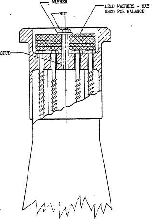
FIGURE 4. Balancing blade.
50 rpm on a machine having an accuracy of
correction for balance in terms of displacement
inch applied in such a manner that no force
of 0.000025 inch, to secure an unbalance of not
other than the mass of the applied balancing or
more than 2.0 ounce-inches in each of two
reversing weight is the indicating feature.
planes.
When equipment other than knife edges is used
3.31.4 Propeller.
the same tolerance shall be applied in an equiv-
Provisions shall be
331.4.1 Provisions.
alent manner.
made for attaching balance weights in each of
3.31.2.1 Ground adjustable. The hubs Shall
two balancing planes located as far apart axial-
be balanced without the clamp rings being
ly as practicable, fore and aft of the plane of the
in place. In order to attain final balance of
blades. Points of attachment must be readily
the finished hub about the axis of the shaft,
accessible with the propeller mounted on the
metal may be removed as shown on the manu-
aircraft.
facturers drawing.
3.31.4.2 Static. The rotation of the propel-
3.31.2.2 Controllable pitch. In the case of
ler caused by out-of-balance shall be stopped
hubs which have been provided with means of
or reversed by an opposite moment. The oppo-
. correcting the unbalance of the completely as-
site moment shall be determined as the weight
sembled propeller, the balancing of the hub
of the propeller times an eccentricity of 0.0005
assembly shall be accomplished with this bal-
inch applied in such manner that no force other
ancing means adjusted to its neutral or mean
than the mass of the applied balancing or re-
position so as to retain its maximum effective-
versing weight is the indicating factor. The
ness for correcting any unbalance of the com-
balance requirement shall be met with any blade
pletely assembled propeller. Other means shall
in a vertical and horizontal position. It is per-
be used to correct any unbalance of the hub
missible to use equipment giving equivalent
accuracy which balances the propeller in a hori-
assembly.
14
|
|
Privacy Statement - Press Release - Copyright Information. - Contact Us |
