 |
|||
|
Page Title:
Table IV. Amplifier input and output signals |
|
||
| ||||||||||
|
|  MIL-P-70995 (AR)
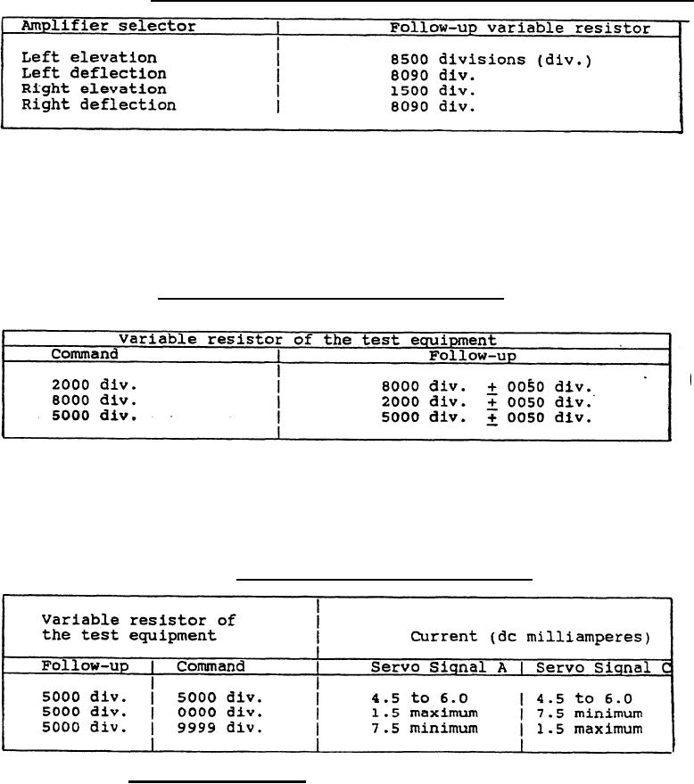
Table III. Test equipment setting to test stow variable resistor.
d. Move the action switch to "on" and the amplifier selector to"
"left elevation".Set the command variable resistor of the test
equipment as specified in Table IV. Adjust the follow-up variable
resistor of the test equipment to obtain a null on the nullmeter. To
be acceptable, the reading on the follow-up variable resistor shall be
in accordance with Table IV for each specified setting of the command
variable resistor. This shall be performed for each of the four
amplifier selections.
Table IV. Amplifier input and output signals.
e. Move the action switch to "on". Set the command variable
resistor and the follow-up variable resistor as specified in Table V.
read the current of servo signal A and servo signal C on the milliam-
meter of the test equipment. To be acceptable, the current of the
servo signal A and servo signal C shall be in accordance with Table V.
This shall be performed for each of the four amplifier selections.
Table V. Siqnal A and signal C current.
4.5.4.3 Armed functioning. The control panel shall be tested for
proper armed functioning as follows:
14
|
|
Privacy Statement - Press Release - Copyright Information. - Contact Us |
