 |
|||
|
Page Title:
Hydraulic pressure and flow test |
|
||
| ||||||||||
|
|  MIL-P-45969B (AR)
4.4
Tests.
4.4.1
Hydraulic pressure and flow test.
a.
Connect power supply AC power cable to 220 VAC 3 phase 50
to 60 Hertz supply and connect a hydraulic pressure gage,
flow meter, and a variable external test load between the
supply and return port. Close the outlet shutoff valve
and open the bypass valve before energizing the power
supply.
b. With master switch in the off position, verify that the
start switch (S2) will not energize the hydraulic system.
Place master switch in the on position and depress start
button. Verify that pump motor (B1) and heat exchanger
fan (B2) are energized. Red indicator lamp (DS2) should
not be illuminated.
c. Adjust external variable hydraulic test load for 0 gpm
flow rate, open outlet shutoff valve and close bypass
valve. Adjust hydraulic pump compensator control to
verify that pressure is continuously variable from 500 to
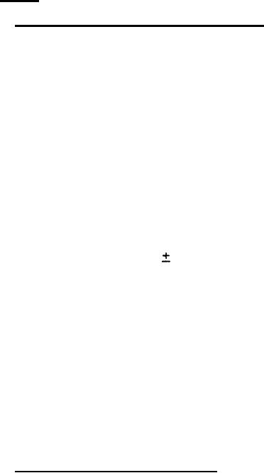
1500 psi. Verify that power supply hydraulic pressure
50 psi of the test pressure gage at
gage reads within
500, 1000 and 1500 psi. Retain setting of 1500 psi.
d. Set the variable Hydraulic external test load for a flow
of 4 gpm or greater. Adjust hydraulic pump volume
control to verify flow is continuously available from 1
to 3.5 gpm. Verify that the power supply hydraulic flow
meter reads within 2 percent of test flow meter at 1, 2,
and 3.5 gpm. Retain setting of 3.5 gpm and lock pump
volume control.
e. Shut outlet shutoff valve and observe 0 gpm flow through
external flow meter and minimum indication on power
supply flow meter. Open bypass valve and observe 3.5 gpm
flow on power supply flow meter. Stop power supply.
f. Inspect power supply for external hydraulic leakage.
External leakage of any component shall not exceed that
specified in 3.4.5.
.
4.4.2 Pressure relief valve test. The test shall be performed
using either Test Method A or Test Method B below. The test method
shall be optional with the contractor except Method B shall be used
only if the power supply is equipped with a pump which is adjustable
to sufficient pressure. After testing, inspect power supply for
external hydraulic leakage. External leakage of any component shall
not exceed that specified in 3.4.5.
a.
Test Method A: With power supply cable disconnected,
connect an external hydraulic pressure source, test
pressure gage, and test flow meter to the power supply
port. Open outlet shutoff valve and close bypass valve.
Increase pressure supplied from external hydraulic source
16
|
|
Privacy Statement - Press Release - Copyright Information. - Contact Us |