 |
|||
|
|
|||
| ||||||||||
|
|  MIL-P-48189D (AR)
APPENDIX A
Operating limits (ambient).
30.4
OSC. FREQ.
TEMPERATURE
VOLTAGE
CURRENT (RUN)
+25C
NOMINAL 1%
40 MICRO AMPS
4.O V
30.5 VB rise time and tolerance. The rise time on VB shall be
greater than 1 mil llsecond and less the 500 millisecond to 96% of
its final value. Tolerance on
is .05 VOLTS.
40.
SYSTEM TESTS PROCEDURE
System Tests shall be performed in accordance with Table I in a
manner which meets the intent of the referenced requirement
paragraph.
40.1 Table 1.
Test procedure.
40.2
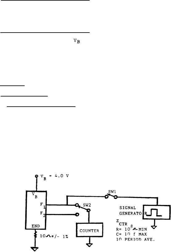
40.2.1 Oscillator frequency. The oscillator frequency shall be
measured by connecting the S.U.T. (System Under Test) as shown in
Figure 1. The counter shall have an input impedence of 108 ohms
or greater (C=10pf max) and the measurement shall represent a 10
period average. Frequency of both F1 and F2 shall be measured, and
be within the limits of Table I. Input to F1 shall have a minimum
of 1,500 fast counts applied and shall stabilize for 500
milliseconds minimum before the measurement is made. Test
sequence: 1. Close SW1 and allow 1,500 fast counts to enter. 2.
Open SW1 and wait 500 milliseconds minimum. 3. Close SW2 to F1.
4. Measure 10 period average of F1. 5. Close SW2 to F2. 6.
Measure 10 period average of F2.
Figure 1. Oscillatory frequency measurement.
73
|
|
Privacy Statement - Press Release - Copyright Information. - Contact Us |
