 |
|||
|
|
|||
| ||||||||||
|
|  MIL-P-5238C
4.5.17.1 Dry cut-off endurance. The pump and test rig shall be operated in
a manner similar to the above to cause the dry cut-off feature to actuate.
Seventy-five percent of the cycles shall be with the fuel and air temperatures
as above, and 25 percent shall be with the fuel and air temperature at minus
65F.
4.5.18 Contaminated fuel endurance. An endurance test using contaminated
fuel shall be accomplished in accordance with the solid particle contaminated
fuel endurance test of MIL-F-8615.
4.5.19 Power input tests
4.5. 19.1 Electrical power variations. The power input, temperature rise,
fuel flow and pressure output shall be determined by test for all power
variations in the electrical system of the aircraft in accordance with the
detail specification.
4.5.19.2 Hydraulic power variations. The power input, pump speed, fueI flow,
and pressure output shall be determined by test for the possible power varia-
tions in the hydraullc system of the aircraft. The testing shall be in a
system with characteristics of MIL-H-5440 or MIL-H-8891, as applicable, and
the detail specification.
4.5.19.3 Start-up. Electric powered pumps shall be tested to determine that
the current and voltage transients are within the approved limits. Hydraulic
powered pumps shall be tested to determine that the starting acceleration (wet
and dry) is within the approved limits and that no parts are overstressed.
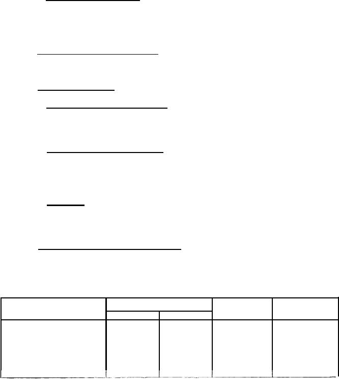
4.5.20 Electrical insulation resistance. The insulation resistance and
dielectric strength tests shall be conducted in accordance with MIL-STD-202,
Method 301, using table III and Method 302, Condition B. There shall be no
disruptive discharges, excessive leakage current or low resistance.
TABLE III.
Dielectric Test Voltages
Repeat Tests
80,000 Ft
Initial, Test
System Voltage
1 Minute
10 Seconds
10 Seconds
1 Minute
1250
500
500
1050
28 VDC
600
500
1250
1500
115 VAC
700
1500
1800
700
115/200 VAC
16
|
|
Privacy Statement - Press Release - Copyright Information. - Contact Us |
