 |
|||
|
|
|||
| ||||||||||
|
|  MIL-P-62341/3A
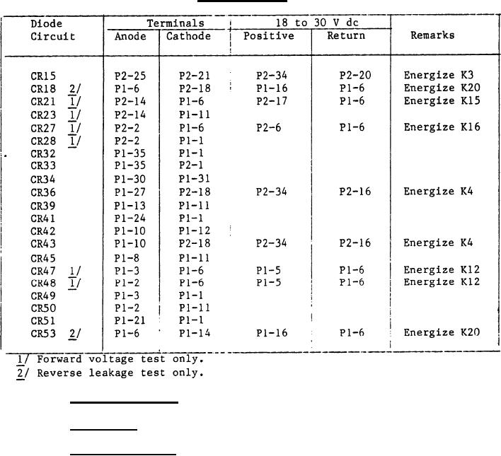
TABLE II. Diode circuits - Continued.
3.5.4 Blocking diodes. Not applicable.
Not applicable.
3.5.5 Resistors.
3.5.6 Relay operation. Relays shall energize when 18 to 30 V dc is
applied to the terminals specified in tables III and IV. With 18 to 30 V dc
applied to the relay contact terminals specified in tables III and IV and
with a 560 56 ohm resistor connected between the relay contact return
terminal and the relay contact power supply return terminal, the voltage drop
across the resistor shall be as specified in tables III and IV. Unless
otherwise specified herein, VH shall be within 0.5 V dc of the contact supply
voltage and VL shall not exceed 0.5 V dc. The voltage sequences of table IV,
column 6 are defined for uninterrupted application of power to the terminals
specified in columns 3, and 5 except where changes are indicated as the
sequence progresses (see 4.8.4.7).
3
|
|
Privacy Statement - Press Release - Copyright Information. - Contact Us |
