 |
|||
|
|
|||
| ||||||||||
|
|  MIL-PRF-62365C(AT)
4.5.4.4 Fungus. The assembly shall be tested in accordance with MIL-STD-810,
method 508.3, to verify conformance to 3.5.4. In lieu of the performance of the MIL-STD-810
test, certification of compliance, with supporting data, may be provided attesting that the
assembly is constructed of materials that will not support fungus growth.
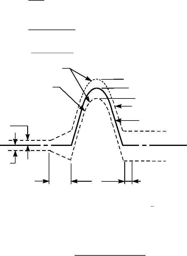
4.5.4.5 Shock (nonoperating). To determine conformance to 3.5.5, the motor shall fall
within the tolerance envelope of figure 1 when exposure to the half-sine shock waves of 25 g for
11 milliseconds (ms) duration applied along three mutually perpendicular directions.
4.5.4.5.1 Frequency response. The frequency response of the complete measuring
system, including the transducer through the readout instrument shall be as specified in figure 2.
Tolerance limits
1.15A
Sine wave translated
A
down to 0.15A
0.85A
Sine wave translated
up to 0.15A
Ideal sine wave
0.05A
0.2A
Reference
line zero
0.2A
0.05A
0.1D
0.4D
D
Vi = 2AD/š
V = Vi + 10%
NOTE:
The oscillogram should include a time about 3D long with pulse located approximately in the
center. The integration to determine velocity change should extend from 0.4D before the pulse to
0.1D beyond the pulse. The acceleration amplitude of the ideal half-sine pulse is A and its
duration is D. Any measured acceleration pulse which can be contained between the broken line
boundaries is a nominal half-sine pulse of nominal amplitude A and nominal duration D. The
velocity-change associated with the measured acceleration pulse is V.
FIGURE 1. Tolerances for half-sine shock pulse.
15
|
|
Privacy Statement - Press Release - Copyright Information. - Contact Us |