 |
|||
|
Page Title:
Performance at specific temperatures |
|
||
| ||||||||||
|
|  MIL-P-82534(OS)
c. Apply positive resaturation voltage of 0.210 plus or minus 0.010
volt DC until 4 volts DC is obtained at contacts S and A of connec-
tor 1A1J1. The 0.210 volt DC is supplied by the programmer
across contacts S and L (positive) of connector 1A1J1. The
appearance of 4 volts DC across contacts S and A is indicated by
the stopping of the tester counter. Observe readback time on
the counter.
4.6.1.4.6 Performance at specific temperatures. Place the programmer
in the temperature chamber specified in 4.4.1d. Perform the following tests
while the programmer is stabilized at each of the temperatures listed in Table II
for 4 hours minimum.
a. Channel one readback time: take six consecutive readings at each
channel one set-in voltage and temperature listed in Table II.
Tabulate the last five of the six readings and then calculate the
RMS error. (See 6.3.2.) The RMS error shall not exceed that
specified in Table II.
b. Channel two readback time: take six consecutive readings at each
channel two set-in voltage and temperature listed in Table II.
Tabulate the last five of the six readings and then calculate the
RMS error. (See 6.3.2.) The RMS error shall not exceed that
specified in Table II.
4.6.1.4.7 Output energy. Energize the programmer as specified in
4.6.1.4. Connect a mercury switch and a 2 ohm, 1 watt, 1 percent resistor
in series across contacts S and d of connector 1A1J1. Attach the vertical input
lead of the oscilloscope specified in 4.4.1e to contact d. Set the oscilloscope
vertical sensitivity control at 5 volts per centimeter. Set the oscilloscope hori-
zontal sensitivity control at 1 millisecond per centimeter. Using the oscillo-
scope camera, observe and record the output energy pulse of the programmer.
The output energy, as computed in 4.6.1.4.7.1, shall be not less than 2 million
ergs.
4.6.1.4.7.1 Output energy calculation procedure. From the photographic
record of the output energy pulse, measure the output voltage at 0.50, 1.50,
and 2.50 milliseconds from the beginning of the pulse and identify the measure-
ments as E1, E2, and E3 respectively, see Figure 3. The energy content of
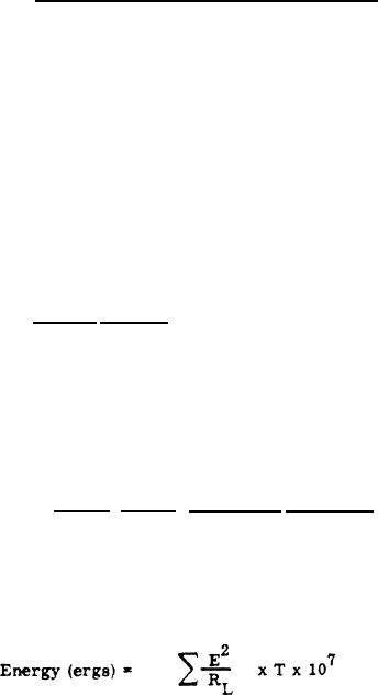
the programmer output energy pulse is defined here as the summation of
energy increments calculated from the three voltages and the three one-millisecond
time intervals. The basic energy equation is:
18
|
|
Privacy Statement - Press Release - Copyright Information. - Contact Us |