 |
|||
|
Page Title:
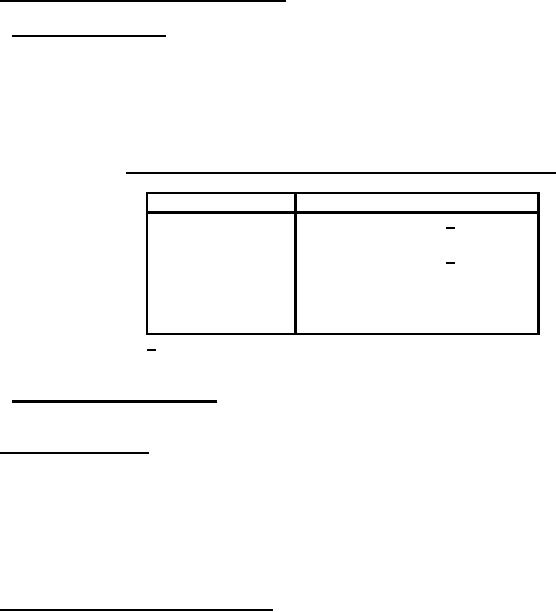
Table VII. Resistance temperature characteristic test ambient temperatures |
|
||
| ||||||||||
|
|  MIL-R-19365D
4.7.3 Resistance temperature characteristic (3.8).
4.7.3.1 Qualification inspection. Resistors shall be tested in accordance with method 304 of MIL-STD -
202. The following detail and exception shall apply:
a. Test temperatures: As specified in table VII.
b. Measurement at end of each period: Total resistance shall be measured as specified in 4.7.1.1, at
the temperature maintained during the period.
TABLE VII. Resistance temperature characteristic test ambient temperatures .
Test ambient temperature (C)
Sequence
1
25 1/
2
-55
3
25 1/
4
125
5
200
6
275
7
350
1/ This temperature shall be considered the reference for
each succeeding temperatures.
4.7.3.2 Product acceptance inspection. Resistors shall be tested as specified in 4.7.3.1, except that
sequences 1, 2, 3, and 7 of table VII shall be performed only, in that order.
4.7.4 Temperature (see 3.9). Resistors shall be placed in an oven at room temperature. The
temperature of the oven shall then be elevated gradually to the maximum hotspot surface temperature of
the resistor +5, -0C (see table I). The period of the transition from room temperature to the hotspot
surface temperature shall be accomplished in not more than 45 minutes. For conformance inspection, at
the option of the manufacturer, the resistors may be placed in an oven whose temperature has already
been brought up to approximately the hotspot surface temperature. The resistors shall be conditioned at
the latter temperature for a two hours. They shall then be allowed to cool gradually to room temperature,
after which they shall be visually examined for evidence of mechanical damage.
4.7.5 Dielectric withstanding voltage (see 3.10). Resistors shall be tested in accordance with method
301 of MIL-STD -202. The following details shall apply:
a. Special preparations: Resistors shall be mounted, without supplementary insulation, between two
metal plates normal to the longitudinal axis of the resistor, one plate at each end, held firmly
against the end of the resistor core by a through bolt. These plates shall be of sufficient size to
extend beyond the resistor terminal extremities. The adjustable terminal shall be positioned within
5 percent of the electrical center.
b. Magnitude of test voltage: 1,000 volts.
20
|
|
Privacy Statement - Press Release - Copyright Information. - Contact Us |