 |
|||
|
Page Title:
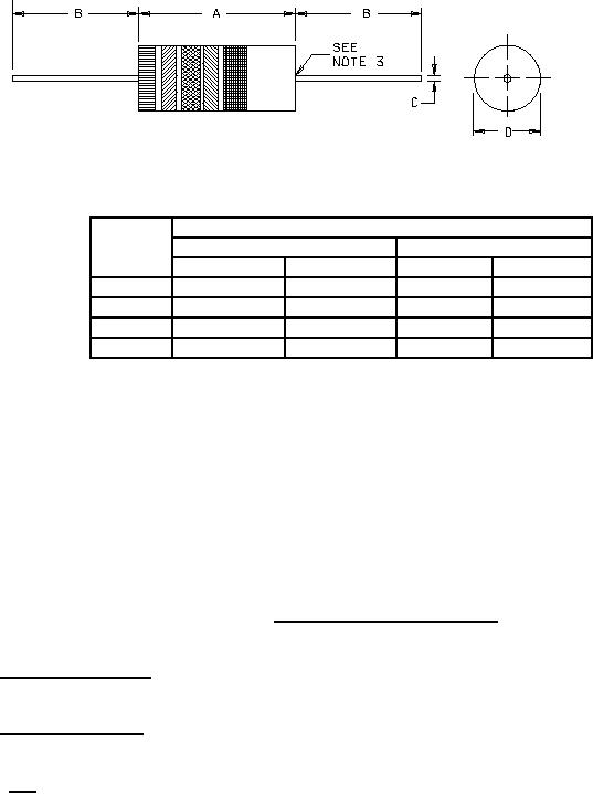
Figure 1. Configuration and dimensions |
|
||
| ||||||||||
|
|  MIL-R-22684/1B
DIMENSIONS
INCHES
MILLIMETERS
MIN
MAX
MIN
MAX
A
.205
.281
5.56
7.14
B
1.375
1.625
34.92
41.28
C
.019
.027
0.48
0.68
D
.082
.098
2.08
2.49
NOTES:
1. Dimensions are in inches.
2. Metric equivalents are given for general information only.
3. The end of the body shall be that point at which the diameter equals the nearest
drill size larger than 250 percent of the nominal lead diameter. The leads shall
be solderable to within .125 inch (3.18 mm) of the resistor body.
FIGURE 1. Configuration and dimensions.
3.8 Insulation resistance. Resistors shall be tested as specified in MIL-PRF-22684 except the
insulation resistance shall be not less than 100 megohms.
3.9 Moisture resistance. Resistors shall be tested as specified in MIL-PRF-22684 except the change in
resistance shall not exceed 1.5 percent.
3.10 Life. Resistors shall be tested as specified in MIL-PRF-22684 except the change in resistance
shall not exceed 2.0 percent.
3
|
|
Privacy Statement - Press Release - Copyright Information. - Contact Us |