 |
|||
|
Page Title:
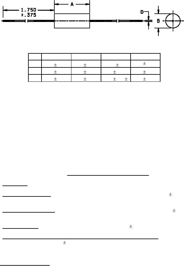
Figure 1. Styles RW70, RW74, RW78, and RW79 |
|
||
| ||||||||||
|
|  MIL-R-26/5C
RW70
RW74
RW78
RW79
.560 .062
A
.406 .031
.875 .062
1.780 .062
B
.094 .031
.312 .031
.375 .031
.187 .031
D
.020 .0015
.040 .002
.040 .002
.032 .002
Inch
mm
Inch
mm
.0015
.04
.187
4.75
.002
.05
.312
7.92
.020
.51
.375
9.53
.031
.79
.406
10.31
.032
.81
.560
14.22
.040
1.02
.875
22.23
.062
1.57
1.750
44.45
.094
2.39
1.780
45.21
NOTES:
1. Dimensions are in inches.
2. Metric equivalents are given for general information only.
3. These styles shall be untapped.
4. The end of the resistor body is the point where the diameter reduces to 0.06 inch.
FIGURE 1. Styles RW70, RW74, RW78, and RW79.
3.11 Solderability. Solderability is applicable to this specification.
3.12 Shock (medium impact). The resistors shall not change in resistance in excess of (0.1 percent
+.05 ohm).
3.13 Vibration (high frequency). The resistors shall not change in resistance in excess of (0.1 percent
+.05 ohm).
3.14 Terminal strength. The resistors shall not change in excess of (0.1 percent +.05 ohm).
3.15 Dielectric withstanding voltage (barometric pressure, reduced, not applicable). The resistors shall
not change in resistance in excess of (0.1 percent +0.05 ohm).
4. VERIFICATION
4.1 Sampling and inspection. Sampling and inspection shall be in accordance with MIL-PRF-26.
5
|
|
Privacy Statement - Press Release - Copyright Information. - Contact Us |