 |
|||
|
Page Title:
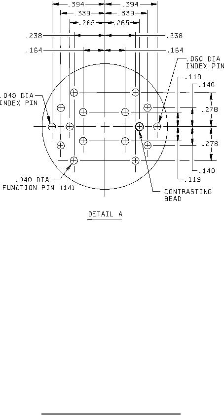
Figure 2. Relay - socket pin configuration (M5757/7-003) - Continued |
|
||
| ||||||||||
|
|  MIL-R-5757/7F
Inches
mm
Inches
mm
Inches
mm
Inches
mm
.040
1.02
.164
4.17
.281
7.14
1.06
26.9
.060
1.52
.203
5.16
.339
8.61
1.14
29.0
.085
2.16
.210
5.33
.357
9.07
1.34
34.0
.119
3.02
.238
6.05
.36
9.1
1.406
35.71
.138
3.51
.265
6.73
.388
9.86
1.69
42.9
.140
3.56
.278
7.06
.394
10.01
NOTES:
1. Dimensions are in inches
2. Unless otherwise specified, tolerance is .010 (0.25 mm).
3. Metric equivalents are given for general information only.
4. All active electrical terminals shall be gold plated 0.00005 (50 microinches) minimum. One system for gold
plating that may be used is ASTM B488, type 3, class 1.25 with a nickel underplate of 50 to 150 microinches
thick. Gold plating of index pins is optional. The gold plating system shall enable the product to meet the
performance requirements of this specification and shall be approved by the qualifying activity.
FIGURE 2. Relay - socket pin configuration (M5757/7-003) - Continued.
4
|
|
Privacy Statement - Press Release - Copyright Information. - Contact Us |
