 |
|||
|
Page Title:
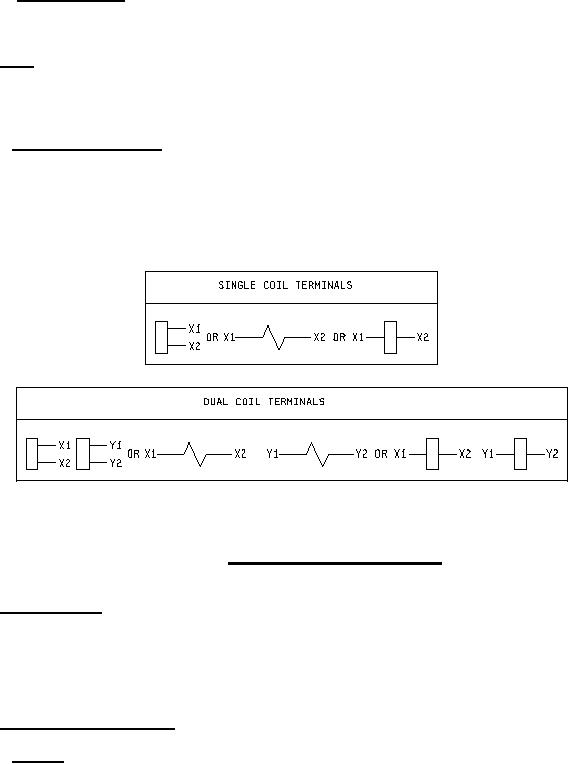
Figure 1. Terminal symbols and markings |
|
||
| ||||||||||
|
|  MIL-R-5757H
3.4.3.2. Switch capsules. Unless otherwise specified (see 3.1), switch capsules used in dry reed
relays shall be such that the performance requirements of this specification are met. Switch capsule
leads shall not be used as terminals.
3.4.4 Coils. Coils shall be adequately insulated electrically from the contacts and the case. The
resistance and rated voltage (or current) shall be as specified (see 3.1). Coils shall be designed for
continuous operation at maximum rated voltage (or current) and temperature, unless otherwise specified
(see 3.1).
3.4.4.1 Terminal identification. When specified (see 3.1), a bead of contrasting color shall be used to
designate the X1 (positive, if applicable) terminal (see figure 1 and MIL-STD-1285).
FIGURE 1. Terminal symbols and markings.
3.4.5 Circuit diagram. The circuit diagram as specified (see 3.1), shall be a terminal view. Circuit
symbols shall be in accordance with ANSI Y32.2. For relays without an orientation tab, the circuit
diagram, as specified (see 3.1), shall be oriented so that when the relay is held with the circuit diagram
right side up as shown (see 3.1), and rotated away from the viewer about a horizontal axis through the
diagram until the header terminals face the viewer, then each terminal shall be in the location shown in
the circuit diagram.
3.4.6 Mounting means (see 3.1).
3.4.6.1 Bracket. Mounting brackets shall be an integral part of the relay, securely attached thereto in a
manner to prevent any movement between the relay and the mounting bracket.
5
|
|
Privacy Statement - Press Release - Copyright Information. - Contact Us |