 |
|||
|
|
|||
| ||||||||||
|
|  MIL-R-5757H
3.4.7.1 Solder-lug terminals. Solder-lug terminals shall be designed to accommodate two conductors,
each rated to carry the maximum rated current of the contact or coil terminated.
3.4.7.2 Wire leads. Wire leads shall be as specified (see 3.1). Optional, shortened wire leads may be
supplied when specified on the individual order (see 3.1 and 6.2.1b).
3.4.7.2.1 Wire leads, solder pin (SP). Solder pin wire leads shall be as specified (see 3.1).
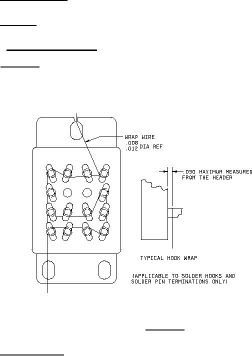
3.4.7.3 Wire marks. When plating is used, an underplating of copper may be used to assure good
adhesion. A slight exposure of copper underplating or other underplating resulting from wire wrapping
necessitated by the plating operation is acceptable (see figure 3).
FIGURE 3. Wire marks.
3.4.7.4 Plug-in termination. Plug-in terminations shall conform to the arrangements or dimensions as
specified (see 3.1). The mounting arrangement of the relay shall be so designed that the entire weight of
the relay will be suspended and the stability of its mounting will be provided by an auxiliary mounting
means other than the electrical terminals of a socket (see 3.1). Plug-in terminals shall be gold plated in
accordance with MIL-G-45204, type II, class I, with a nickel underplating that shall be in accordance with
QQ-N-290 and 50 microinches to 150 microinches thick.
7
|
|
Privacy Statement - Press Release - Copyright Information. - Contact Us |
