 |
|||
|
Page Title:
Thermal shock (high and low temperature operation) |
|
||
| ||||||||||
|
|  MIL-R-83407B
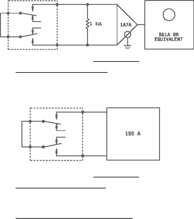
FIGURE 2. Contact noise test circuit.
4.5.12 Thermal EMF (when specified) (see 3.1 and 3.15). Thermal EMF shall be measured on each contact
which closes when the relay is energized and deenergized respectively. Rated voltage shall be used to energize the
relay. Each thermal EMF measurement shall be made for approximately 30 minutes after the relay is energized or
deenergized. When the relay incorporates more than one contact pole, as many as two closed contacts may be
connected in series and measured at a given time. A suitable test circuit is shown in figure 3 for two contacts in
series.
FIGURE 3. Thermal EMF test circuit.
4.5.13 Capacitance (when specified) (see 3.1 and 3.16). Relays shall be tested in accordance with method 305
of MIL-STD-202. The following details apply:
a. Test frequency: 1 kHz.
b. Points of measurement: See 3.1.
4.5.14 Thermal shock (high and low temperature operation) (see 3.17). Relays shall be tested in accordance with
method 107 of MIL-STD-202. The following details and exceptions apply:
a. Special mounting: Relays shall be suspended in the test chamber by twine or other nonheat- conducting
material, in a plane parallel to the normal air flow. Test leads may be used for mounting; however, they shall
not provide a heat sink.
b. Test condition: B, except temperature range shall be as specified (see 3.1), and exposure time at
temperature extreme during the fifth cycle shall be 2 hours each.
c. Measurements at each temperature extreme during steps 1 and 3 of the fifth at the end of each temperature
exposure, and with the relays still in the conditioning chamber, the insulation resistance, pickup and dropout
voltages, and operate and release times, shall be measured as specified in 4.5.4, 4.5.6, and 4.5.9,
respectively.
11
|
|
Privacy Statement - Press Release - Copyright Information. - Contact Us |
