 |
|||
|
|
|||
| ||||||||||
|
|  MIL-S-17000N(SH)
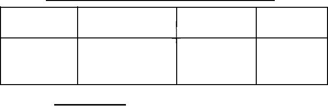
Ampere rating of rectangular bus bars placed on edge. - Continued
TABLE IV.
Size of bars
Cross sectional
A.c. ampere
D.c. ampere
(inches)
rating
rating
area
(inZ)
3
x
1/4
0.750
1,140
1,185
4
x
1/4
1,490
1 .000
1,425
5
x
1/4
1.250
1,760
1,850
2,190
6
X
1/4
1.500
2,100
3.6.23.8 Bus bar stresses. The bus work assembly shall withstand the
stresses resulting from the maximum available root mean square (rms) asym-
metrical short-circuit current (see 6.2.1). Conditions of H.I. shock which
may be encountered aboard the ship shall not mechanically damage the bus work
or reduce the bus clearances below minimum requirements. Where single conductor
cable is used for connection between bus bars and supply switches, the cable
shall be securely bound together with nonflammable cord and secured to the
supports as necessary to prevent distortion under short circuit conditions.
The binding shall be applied in such a manner that it will not cut into the
cable insulation due to the forces exerted under short circuit conditions.
The binding shall be especially heavy where cables turn out of the pack.
Terminal lugs shall be used for terminating cable at the switch terminals and
at the bus bars. Through-bolts shall be used for securing the cable terminal
to the bus bars. Not more than two cable terminals shall be clamped by one bolt,
and when two are used, they shall be placed on opposite sides of the bus. The
cables shall be neatly formed, and where their length exceeds approximately
12 inches, they shall be supported by the switchboard structure. For calcula-
tion of required spacing of bus supports to withstand the short circuit current,
the value of maximum stress in the outside fiber shall be based on the yield
strength of the copper and not upon the tensile strength.
3.6.23.9 Bus bars shall be accurately formed and holes shall be accurately
made so as to ensure that the bus bars can be fitted into place without being
forced. Flat bends shall have an inside radius of not less than the thickness
of bus bar, and the ends of the bus bars shall be neatly finished. Edgewise
bends of bars up to 2 inches in width may be made on an inside radius of 1 inch,
and those over 2 inches but not exceeding 4 inches in width may be made on an
inside radius of 2 inches. Bars of greater width cannot be bent edgewise, but
shall be bolted. Bars shall be free from cracks or flaws at bends.
3.6.23.10 Holes in bus bars for bolting may be
either punched or drilled,
but the contact areas shall be finished true, or an
equivalent method employed
to give adequate contact. Contact nuts and contact
spaced nuts for copper stud
contacts shall be of sufficient size to provide the
necessary contact surface
area.
in bus bar joints shall be of steel, coarse
3.6.23.11 Bolts and nuts, used
against corrosion. Flat washers of
thread series, and plated to protect
under all bolt heads and nuts adjacent to
similarly plated steel shall be used
be fitted with a securing nut and a lock
the conductor. Securing bolts shall
nut.
36
|
|
Privacy Statement - Press Release - Copyright Information. - Contact Us |
