 |
|||
|
Page Title:
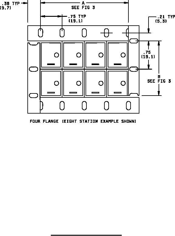
Figure 1: Matrix frame assembly, rear mount - Continued |
|
||
| ||||||||||
|
|  MIL-S-24317/12B
NOTES:
1. Dimensions are in inches. Metric equivalents are in parentheses and are given for general
information only.
2. Unless otherwise specified, tolerances are .015 (.38 mm) for three place decimals and .03
(.76 mm) for two place decimals.
3. For matrix and panel cutout dimensions, see figure 3.
4. Design configuration is optional within envelope dimensions shown.
5. To remove pushbutton, move Latch to right.
6. Single rows or columns of sever or more station with rear mounting flanges will be furnished with
two stiffener straps of aluminum alloy, .06 (1.52) thick X 0.5 (12.70) wide (styles S, W, L and C).
7. All housings are constructed to accept a captive pushbutton lens assembly. Therefore, the
housing and module assemble can be installed and the captive pushbutton option can be added
or removed at any time.
8. Index post provided prevents incorrect insertion of pushbutton into switch module.
9. Module mounting screw is provided with MIL-PRF-22885/105 switch module.
FIGURE 1: Matrix frame assembly, rear mount - Continued.
3
|
|
Privacy Statement - Press Release - Copyright Information. - Contact Us |
