 |
|||
|
Page Title:
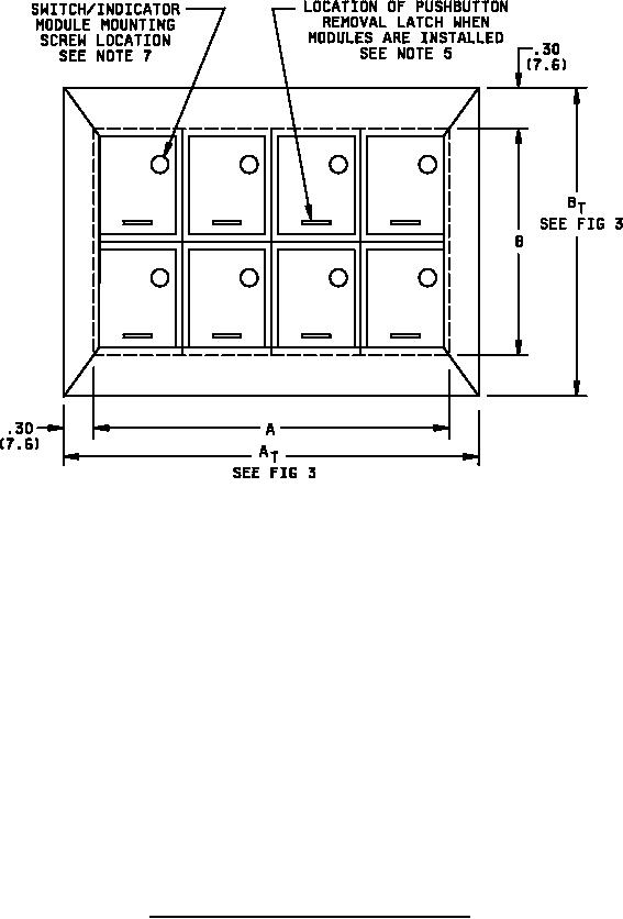
Figure 2: Matrix frame assembly - dress bezel mount cont'd |
|
||
| ||||||||||
|
|  MIL-S-24317/12B
NOTES:
1. Dimensions are in inches. Metric equivalence are in parentheses and are given for general
information only.
2. Unless otherwise specified, tolerances are .015 (.38 mm) for three place decimals and .03
(.76 mm) for two place decimals.
3. For matrix and panel cutout dimensions, see figure 3.
4. Design configuration is optional within envelope dimensions shown.
5. To remove pushbutton, move Latch to right.
6. All housings are constructed to accept a captive pushbutton lens assembly. Therefore, the
housing and module assembly can be installed and the captive pushbutton option can be added
or removed at any time.
7. Module mounting screw is provided with MIL-PRF-22885/105 switch module.
8. The recommended number of mounting cleat assemblies, plus one extra, shall be provided with
each matrix frame.
9. The recommended tightening torque for mounting cleat screws is 7 inch-pounds (.79 N.m)
FIGURE 2: Matrix frame assembly - dress bezel mount - Continued.
6
|
|
Privacy Statement - Press Release - Copyright Information. - Contact Us |
