 |
|||
|
Page Title:
Figure 2. Lamp and 4PDT switch schematic |
|
||
| ||||||||||
|
|  MIL-S-24317/9B
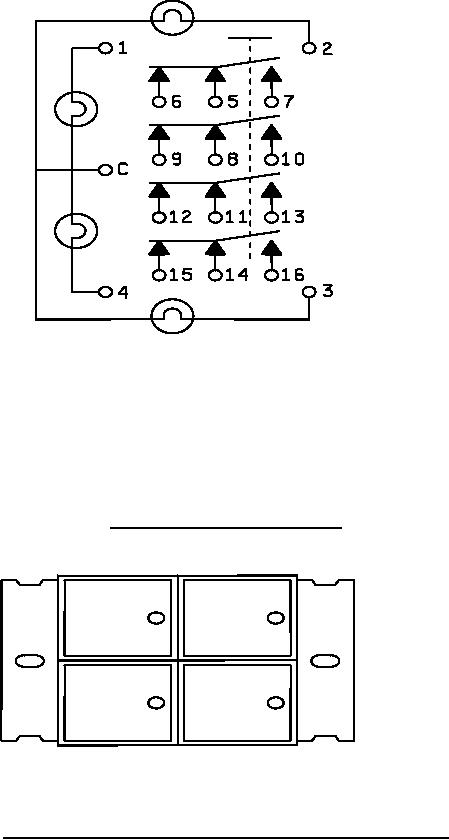
NOTES:
1. Terminals 8 through 13 are omitted for 2PDT configurations.
2. Terminals 5 through 16 are omitted for indicator configurations.
3. Terminals 5, 8, 11, and 14 are pole terminals.
FIGURE 2. Lamp and 4PDT switch schematic.
FIGURE 3. Flange arrangement for unshielded switch (vertical flanges shown).
3
|
|
Privacy Statement - Press Release - Copyright Information. - Contact Us |
