 |
|||
|
|
|||
| ||||||||||
|
|  MIL-S-26547C
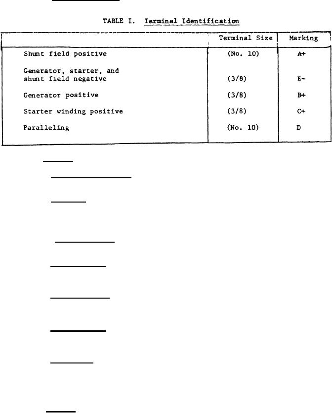
The terminals shall be located and marked as
3.4.7.1 Terminal marking.
shown on Figure 3.
3.4.8
Brushes.
Brush accessibility. Brushes shall be accessible for inspection
3.4.8.1
and replacement when brush cover bands are removed (see Figure 3).
3.4.8.2 Brushfit. The face of each brush shall contact its commutator
100 per cent in the direction of rotation and for at least 75 per cent of
brush dimension parallel to the shaft. There shall be no evidence of grooving
or other surface damage to the face of the brush.
Cartridge type. The brushes in cartridge-type brush assemblies
3.4.8.3
shall not rotate when mounted.
3.4.8.4 Spare brushes. All spare brushes shall be formed to a radius
equal to the radius of the new commutator and shall be identical to the
corresponding brushes approved by the qualification tests.
3.4.8.5 Brush position. The brush rigging shall be fixed position (non-
shifting) type. The brush rigging position shall be identical for all genera-
tors of the same model number made by the same manufacturer.
3.4.8.6 Brush marking. Each brush shall have a diagonal groove in the
anti-drive side, from the contact surface to a point on the front or back of
the brush, which indicates 100 per cent of allowable wear.
3.4.8.7 Brush type. Brushes shall be of the immediate filming type which
do not require prolonged operation of the starter-generator to establish an
altitude protective film on the commutator. Rivets used to secure the leads
to the brushes shall be silver soldered to the pigtail at point of riveted
contact.
* 3.4.9
Cooling. For generator operation, cooling air shall be provided
through a 2 inch diameter duct which shall not be a part of the starter-
generator. The starter-generator shall include provisions for entrance of
external air for cooling purposes through the anti-drive end, or brush access
windows. When cooling air is required to enter through the anti-drive end,
5
|
|
Privacy Statement - Press Release - Copyright Information. - Contact Us |
